
Centering Workbench

A workbench, centering technology, applied in the direction of machine/support, supporting machine, mechanical equipment, etc., can solve the problems of inability to realize, inconvenient detection and operation, and achieve the effect of thorough detection and convenient detection process.

Inactive Publication Date: 2015-09-23
CHONGQING NORMAL UNIVERSITY
View PDF7 Cites 0 Cited by
  • Summary
  • Abstract
  • Description
  • Claims
  • Application Information

AI Technical Summary

Problems solved by technology

[0002] A workbench is a platform for positioning workpieces or experimental samples for processing and testing. The workbench in the prior art is generally a fixed table structure, but in actual processing and testing, it usually needs to be carried out from different directions, for example Applied to the workbench of the biological laboratory. When the rat is used as the experimental sample and the surgical diagnosis and treatment are performed on the eyeball of the rat, it is necessary to position the rat on the workbench and use instruments such as a surgical microscope or OCT detector to detect the recovery of the eyeball. However, in order to achieve comprehensive and thorough detection, it is necessary to observe from different directions centered on the eyeball of the rat, but when carried out on the workbench in the prior art, the multi-directional comprehensive detection can only be realized by means of mobile detection equipment. It not only brings inconvenience to the detection operation, but also cannot realize the above-mentioned operation when using a large-scale vertical detection instrument that cannot be moved

Method used


Image

  • Centering Workbench

Examples


Embodiment Construction

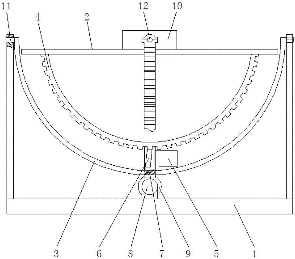
[0017] figure 1 It is a structural schematic diagram of the present invention, as shown in the figure: the centering type workbench of the present invention includes a base 1 and a self-centering assembly installed on the base; the self-centering assembly includes a sample holder 2, and a base 1 is rotationally connected with the sample holder 2 through the coronal axis 11 and the intermediate support 3 is rotationally connected with the sagittal axis 12, and the first drive assembly for driving the sample holder to rotate around the sagittal axis and the intermediate support for driving The rotating second drive assembly fixes the detection site of the sample on the sample holder 2 corresponding to the intersection of the coronal axis 11 and the sagittal axis 12, and drives the intermediate support 3 and the sample through the cooperation of the first drive assembly and the second drive assembly. The linkage of the fixed seat 2 can realize the multi-degree-of-freedom rotation...


PUM


Abstract

The invention discloses a centering workbench. The centering workbench comprises a base and a self-centering component mounted on the base, and the self-centering component comprises a sample fixing seat, a middle support, a first driving component and a second driving component, wherein the middle support is rotatably connected with the base through a coronal shaft and is rotatably connected with the sample fixing seat through a sagittal shaft, the first driving component is used for driving the sample fixing seat to rotate around the sagittal shaft, and the second driving component is used for driving the middle support to rotate around the coronal shaft. The centering workbench is capable of positioning samples and driving the samples to rotate in multiple degrees of freedom by centering on detection portions of the samples, detection from multiple viewing angles can be achieved without movable detection equipment, a detection process is convenient and rapid, and comprehensive and thorough detection can be achieved.

Description

technical field [0001] The invention relates to a workbench, in particular to a centering workbench. Background technique [0002] A workbench is a platform for positioning workpieces or experimental samples for processing and testing. The workbench in the prior art is generally a fixed table structure, but in actual processing and testing, it usually needs to be carried out from different directions, for example Applied to the workbench of the biological laboratory. When the rat is used as the experimental sample and the surgical diagnosis and treatment are performed on the eyeball of the rat, it is necessary to position the rat on the workbench and use instruments such as a surgical microscope or OCT detector to detect the recovery of the eyeball. However, in order to achieve comprehensive and thorough detection, it is necessary to observe from different directions centered on the eyeball of the rat, but when carried out on the workbench in the prior art, the multi-directi...

Claims


Application Information

Patent Timeline
Patent Type & Authority Patents(China)
IPC IPC(8): F16M11/12F16M11/18
Inventor 胡建明丁帅军谭波杨盼张玉崔玉亭梁一平
Owner CHONGQING NORMAL UNIVERSITY
Learn More