Slot-type dual-axial sun tracking heat collecting device

A heat collector, biaxial technology, applied in the field of auxiliary equipment for solar heat collection, can solve the problems of low utilization rate in the horizontal direction, cumbersome tracking control, increase equipment energy consumption, etc., so as to improve the utilization rate of light and heat and reduce tracking Energy consumption, the effect of reducing energy consumption

Active Publication Date: 2015-01-21
合肥耀辉太阳能热力工程科技有限公司
View PDF5 Cites 0 Cited by
  • Summary
  • Abstract
  • Description
  • Claims
  • Application Information

AI Technical Summary

Problems solved by technology

[0002] At present, the trough tracking device mostly adopts a single-axis tracking design structure. The first method is to place it in the overall east-west direction to track the sun's azimuth direction. It cannot track the horizontal direction with the change of the sun's altitude angle, and its horizontal utilization rate is low. Low; the second method is to place it in the overall north-south direction, and use the rolling method to track the sun in the horizontal direction, and the utilization rate of the azimuth direction is also relatively low
The patent CN201985124U dual-axis tracking trough bracket adopts a horizontal rotation mechanism with an electric push rod. This kind of tracking mechanism adopts east-west rotation and north-south push rods. When the east-west rotation is tracked, it will affect the north-south sun elevation angle, resulting in north-south Repeated tracking of direction push rods; the two columns of tracking affect each other, resulting in cumbersome and complicated tracking control, and at the same time increasing the energy consumption of the equipment; it is not conducive to the simultaneous control of time control and light control

Method used


Image

  • Slot-type dual-axial sun tracking heat collecting device
  • Slot-type dual-axial sun tracking heat collecting device
  • Slot-type dual-axial sun tracking heat collecting device

Examples


Embodiment Construction

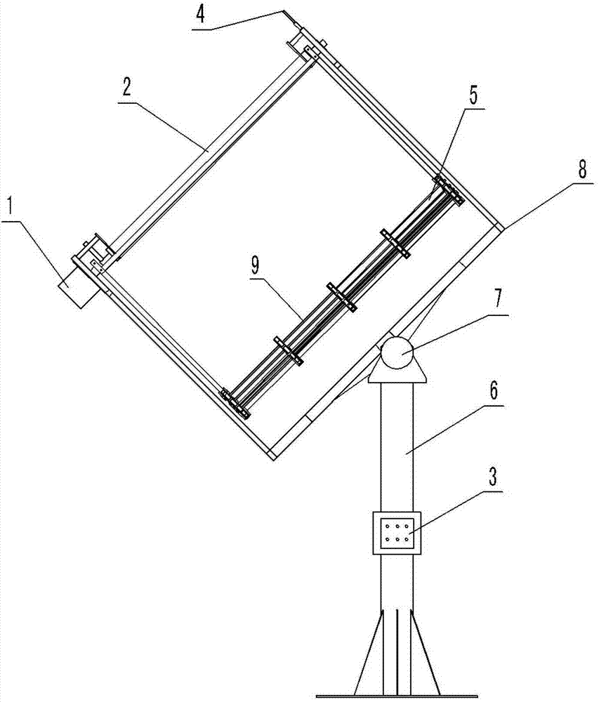
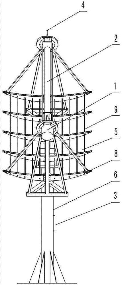
[0016] see figure 1 and figure 2 , the structure of the trough-type biaxial daily tracking heat collector in this embodiment is set as follows: the two tracking power sources are respectively the trough deceleration motor 1 and the tilting deceleration motor 7; the trough deceleration motor 1 and the tilting deceleration motor 7 Drive the rotation of the trough mirror turret 9 and the north-south turret 8 respectively;

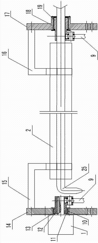
[0017] Such as image 3 As shown, the heat collecting tube 2 is fixed on the left bracket 15 and the right bracket 16, and the heat transfer medium tube 25 is placed in the heat collecting tube 2; the sun azimuth tracker 4 is installed on the upper end of the north-south turret 8; the tracking control cabinet 3 is arranged on the base 6 Above: the sun azimuth tracker 4, the pitch reduction motor 7 and the trough frame reduction motor 1 are connected with the tracking control cabinet 3 by wires.

[0018] Such as Figure 4 As shown, the tilting reduction mo...


PUM


Abstract

The invention discloses a slot-type dual-axial sun tracking heat collecting device. The slot-type dual-axial sun tracking heat collecting device is characterized in that two tracking power sources are respectively a slot rack gear motor and an inclined bending gear motor, and the slot rack gear motor and the inclined bending gear motor can respectively drive a slot-type mirror rotating rack and a north-and-south rotating rack to rotate; a heat collecting pipe is fixed on a left support and a right support, and a heat-conducting medium is placed in the heat collecting pipe; a sun direction tracker is arranged on the upper end of the north-and-south rotating rack, and a tracking control cabinet is arranged on a base; and the sun direction tracker, the inclined bending gear motor and the slot rack gear motor are connected with the tracking control cabinet through power lines. The slot-type dual-axial sun tracking heat collecting device provided by the invention has the advantages that a dual-shaft tracking design structure is adopted, the real-time tracking of light control and time control of the sun is formed through the movement superposition of the slot rack gear motor and the inclined bending gear motor, the sunward tracking accuracy of the device is improved, and a heat collecting effect of the device is improved.

Description

technical field [0001] The invention relates to auxiliary equipment for solar heat collection, in particular to a sun-tracking heat collection device of a trough-type tracking device. Background technique [0002] At present, the trough tracking device mostly adopts a single-axis tracking design structure. The first method is to place it in the overall east-west direction to track the sun's azimuth direction. It cannot track the horizontal direction with the change of the sun's altitude angle, and its horizontal utilization rate is low. The second method is to place it in the north-south direction as a whole, and use the rolling method to track the sun in the horizontal direction, and the utilization rate of the azimuth direction is also relatively low. The patent CN201985124U dual-axis tracking trough bracket adopts a horizontal rotation mechanism with an electric push rod. This kind of tracking mechanism adopts east-west rotation and north-south push rods. When the east-we...

Claims


Application Information

Patent Timeline
Patent Type & Authority Patents(China)
IPC IPC(8): F24J2/38F24S50/20
CPCY02E10/47
Inventor 王国良梁勇
Owner 合肥耀辉太阳能热力工程科技有限公司
Why Eureka
Try Eureka