Eureka AIR delivers breakthrough ideas for toughest innovation challenges, trusted by R&D personnel around the world.

Intelligent high-voltage reactive power automatic adjustment and compensation device

A compensation device and automatic device technology, applied in reactive power compensation, reactive power adjustment/elimination/compensation, etc., can solve the problems of large switching capacity of the compensation capacitor bank, failure of the capacitor bank to be put into operation, and low system power factor. Achieve the effects of small voltage flicker and waveform distortion, which is conducive to safe operation and improved operating conditions

Active Publication Date: 2016-05-25
浙江亿安电力电子科技有限公司
View PDF4 Cites 0 Cited by
  • Summary
  • Abstract
  • Description
  • Claims
  • Application Information

AI Technical Summary

Problems solved by technology

[0005] The disadvantage of this traditional reactive power compensation method is: the switching capacity of the compensation capacitor bank is relatively large, and it can basically meet the requirements of reactive power compensation when it is put into use during peak load. The group cannot be put into operation, the whole group devotes less time
When the compensation capacitor bank is removed, the system power factor is low and the power loss is large, which is not conducive to energy saving and emission reduction

Method used


Image

  • Intelligent high-voltage reactive power automatic adjustment and compensation device
  • Intelligent high-voltage reactive power automatic adjustment and compensation device
  • Intelligent high-voltage reactive power automatic adjustment and compensation device

Examples


Embodiment Construction

[0023] The present invention will be described in further detail below in conjunction with the accompanying drawings.

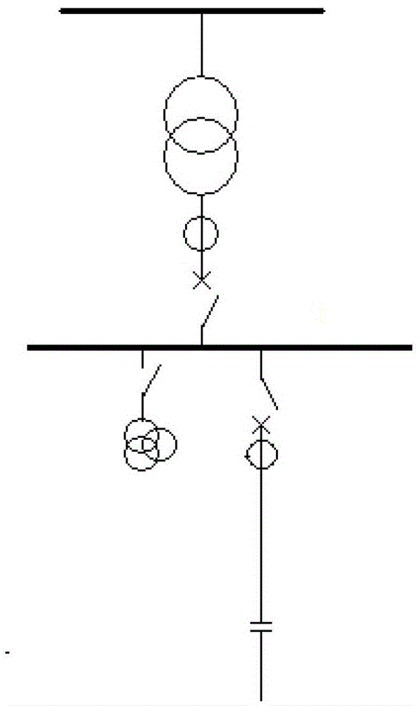
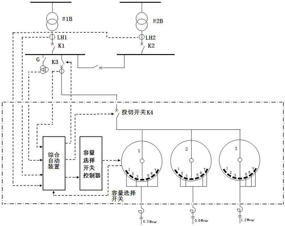
[0024] refer to figure 2 , intelligent high-voltage reactive power automatic capacity adjustment compensation device, including integrated automatic device, capacity selection switch controller, capacity selection switch, switching switch,

[0025] The integrated automatic device is used to measure the reactive load of the main transformer and capacitor bank, calculate the reactive load of the system, and then analyze whether the current operating state of the reactive power compensation device is reasonable according to the reactive load provided by the capacitor bank, and determine the reactive power compensation Whether the capacity is switched to another capacity, when the capacitor needs to be switched to another capacity, an opening signal is sent to the switching switch K4, and when the integrated automatic device detects that the capacitor bank has n...


PUM


Abstract

The invention relates to an intelligent high-voltage automatic capacity adjusting reactive compensation device. The intelligent high-voltage automatic capacity adjusting reactive compensation device comprises a comprehensive automatic device, a capacity selective switch controller, a capacity selective switch and a fling-cut switch, wherein the comprehensive automatic device is used for measuring the reactive loads of a main transformer and a capacitor bank, working out the reactive load of the device, analyzing whether the current operation state of the reactive compensation device is reasonable according to the reactive load provided by the capacitor bank, and determining whether the reactive compensation capacity is switched to another capacity, when capacitors need to be switched to another capacity, the comprehensive automatic device is used for transmitting opening signals to the fling-cut switch, when the comprehensive automatic device detects that no electric current exist in the capacitor bank, the comprehensive automatic device is used for transmitting signals to the capacity selective switch controller, the capacity selective switch controller is used for starting the capacity selective switch and adjusting tap positions, and after the tap positions are adjusted, the comprehensive automatic device is used for transmitting switching signals to the fling-cut switch. The intelligent high-voltage automatic capacity adjusting reactive compensation device has the advantages that the grouping number and the grouping capacity of the capacitors are reasonably set according to the number of taps of an on-load tap-switch, and further, the accuracy of reactive compensation is increased.

Description

technical field [0001] The invention relates to a reactive power compensation device in a power supply system. Background technique [0002] The reactive power compensation device is an important electrical equipment in the power supply system. It is of great significance to improve the power factor of the power supply system, reduce system loss, and ensure power quality. In particular, the dynamic reactive power compensation device can automatically increase or decrease the reactive power compensation capacity according to the load size and power factor to meet the reactive power demand of the system, thereby ensuring the economical operation of the system. [0003] The principle wiring of the traditional reactive power compensation device is as follows: figure 1 Shown: When the load is heavy, the compensation capacitor bank is put into operation, and when the load is lightened, the capacitor bank is cut off to exit the reactive power compensation. [0004] Due to the rel...

Claims


Application Information

Patent Timeline
Patent Type & Authority Patents(China)
IPC IPC(8): H02J3/18
CPCY02E40/30
Inventor 张兴超
Owner 浙江亿安电力电子科技有限公司
Why Eureka
Eureka Blog
Learn More