Horizontal pipe type falling film evaporator

A falling film evaporator, tube type technology, applied in the field of horizontal tube falling film evaporator, can solve the problems of high requirements, blockage of heating tube, inconvenient transportation, etc., to ensure stability, slow down the fluctuation of air flow, and maintain stable supply Effect

Inactive Publication Date: 2014-11-26
四川东联新能源科技有限公司
View PDF1 Cites 0 Cited by
  • Summary
  • Abstract
  • Description
  • Claims
  • Application Information

AI Technical Summary

Problems solved by technology

In the evaporation chamber of the horizontal tube falling film evaporator, the heating steam is located in the condensation tube, and the liquid film is located on the outer wall of the condensation tube. Therefore, during operation, affected by the condensation tube bundle, although there is a certain movement trend for the secondary steam and the feed liquid, there is a certain movement trend at each time point. The specific flow of the MVR evaporation system is relatively complicated, and the flow of the secondary steam and the feed liquid interacts with each other, so the supply of the secondary steam fluctuates; at the same time, the steam compressor of the MVR evaporation system works periodically, especially when the Roots compressor is used , and the periodicity of the steam compressor will further aggravate the fluctuation of the secondary steam supply, which makes the horizontal tube falling film evaporator unable to be used in the MVR evaporation system
[0007] However, in the existing MVR evaporation system using a vertical tube falling film evaporator, the feed liquid flows in the vertical tube falling film evaporator under the dual action of its own weight and steam flow, and the speed is extremely high. In order to ensure high efficiency, heating The length of the tube is usually long, which leads to a large vertical height of the vertical tube falling film evaporator, so the cost of itself and supporting pipelines is high, and limited by the vertical tube falling film evaporator, the miniaturization of the system cannot be realized. And it causes inconvenient transportation and difficult maintenance; secondly, in order to ensure the stable operation of the evaporator, the liquid film must be uniform and stable, and the film cannot be dried or broken in the heating tube. Therefore, the requirements for the distributor and the film distributor are extremely high. It has led to the high cost of the vertical tube falling film evaporator; thirdly, the characteristics and structural characteristics of the vertical tube falling film evaporator make the heating tube easy to foul, and the scaling of the heating tube will affect the heat exchange and even cause the heating tube Therefore, it is necessary to stop the machine for descaling and cleaning, and it also determines that the vertical tube falling film evaporator is not conducive to evaporating high-concentration solutions, especially under the condition of crystalline solid precipitation

Method used


Image

  • Horizontal pipe type falling film evaporator
  • Horizontal pipe type falling film evaporator
  • Horizontal pipe type falling film evaporator

Examples


Embodiment Construction

[0020] The present invention will be further described below in combination with embodiments.

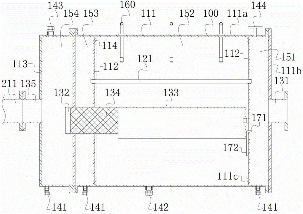
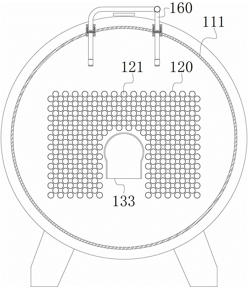
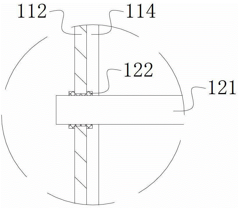
[0021]The horizontal tube falling film evaporator of the present invention comprises a shell 111, two tube sheets 112, a condensation tube bundle 120 and a film distribution device 160; the inner chamber is formed by surrounding the shell 111, and the tube sheets 112 are fixed on the shell 111 inner chamber, along the axial direction of the housing 111, the inner chamber of the housing 111 is divided into a distribution chamber 151, a recovery chamber 153 and an evaporation chamber 152 between the distribution chamber 151 and the recovery chamber 153 by two tube sheets 112; The condensing tube bundle 120 is horizontally arranged in the evaporation chamber 152 along the axial direction of the shell 111, and the two ends of the condensing tube bundle 120 are respectively fixed by the corresponding tube plates 112, and the distribution chamber 151 on both sides of the evaporating chambe...


PUM


Abstract

The invention relates to a pipe type falling film evaporator, and provides a horizontal pipe type falling film evaporator. An evaporation chamber, a distribution cavity and a recycle cavity of the falling film evaporator are mutually isolated closed cavities; condensation pipe bundles are horizontally arranged in the evaporation chamber and used for communicating the distribution cavity and the recycle cavity; a film distribution device is located above the condensation pipe bundles; a concentrated solution outlet is formed in the bottom of the evaporation chamber; condensed water outlets are formed in the bottom of each of the distribution cavity and the recycle cavity; a vapor inlet pipe for communicating the outside and the distribution cavity is arranged, a vapor outlet pipe for communicating the outside and the evaporation chamber is arranged, and a foam destroyer is arranged in the steam outlet pipe. According to the horizontal pipe type falling film evaporator, closed and mutually isolated cavities are formed, so that the stability of an evaporation process, secondary steam and heating steam supply are guaranteed, and the horizontal pipe type falling film evaporator is suitable for MVR (mechanical vapor recompression) vaporization system.

Description

technical field [0001] The invention relates to a tube type falling film evaporator, in particular to a horizontal tube type falling film evaporator. Background technique [0002] There are a large number of evaporation operations in industrial production, especially in chemical, pharmaceutical, papermaking, sewage treatment, seawater desalination and other fields. In the current large-scale industrial production, the evaporation operation usually uses a tubular falling film evaporator to form a multi-effect evaporation system, using high-temperature steam as a heat source for boiling evaporation heated by an indirect heat source. Tubular falling film evaporators are divided into vertical tube falling film evaporators and horizontal tube falling film evaporators according to their structure. The multi-effect evaporation system uses multiple evaporators in series, and each evaporator is called one effect. The raw steam is passed into the first effect evaporator to make the s...

Claims


Application Information

Patent Timeline
Patent Type & Authority Patents(China)
IPC IPC(8): B01D1/22
Inventor 沈洪马永强唐孝东罗昌洪
Owner 四川东联新能源科技有限公司
Why Eureka
Try Eureka