
Centrifugal compressor with asymmetrical vaneless diffuser and automobile with same

A centrifugal compressor and diffuser technology, which is applied to machines/engines, components of pumping devices for elastic fluids, mechanical equipment, etc. Increase the loss and other problems, to achieve the effect of expanding the stable working range, suppressing the stall, and smoothing the flow

Active Publication Date: 2013-09-04
TSINGHUA UNIV +1
View PDF6 Cites 8 Cited by
  • Summary
  • Abstract
  • Description
  • Claims
  • Application Information

AI Technical Summary

Problems solved by technology

In the case of low flow rate, there is a large-scale flow separation phenomenon in the vaneless diffuser. This stall phenomenon increases the flow loss and decreases the efficiency of the diffuser. Under the action of the pressure gradient, the gas flows back and the compressor surges

Method used


Image

  • Centrifugal compressor with asymmetrical vaneless diffuser and automobile with same
  • Centrifugal compressor with asymmetrical vaneless diffuser and automobile with same
  • Centrifugal compressor with asymmetrical vaneless diffuser and automobile with same

Examples


Embodiment Construction

[0031] Embodiments of the present invention are described in detail below, examples of which are shown in the drawings, wherein the same or similar reference numerals designate the same or similar elements or elements having the same or similar functions throughout. The embodiments described below by referring to the figures are exemplary and are intended to explain the present invention and should not be construed as limiting the present invention.

[0032] In describing the present invention, it should be understood that the terms "center", "longitudinal", "transverse", "length", "width", "thickness", "upper", "lower", "front", " Orientation or position indicated by "back", "left", "right", "vertical", "horizontal", "top", "bottom", "inner", "outer", "clockwise", "counterclockwise", etc. The relationship is based on the orientation or positional relationship shown in the drawings, and is only for the convenience of describing the present invention and simplifying the descrip...


PUM


Abstract

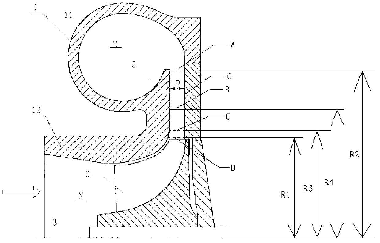
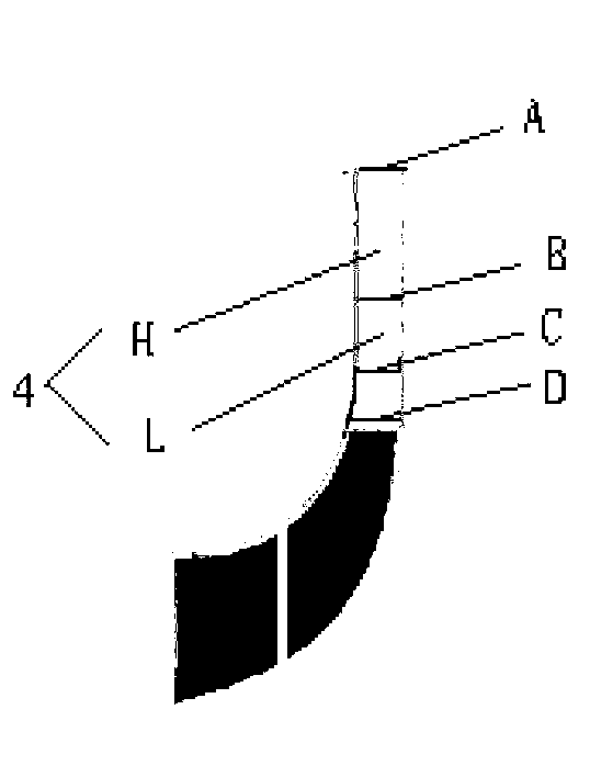
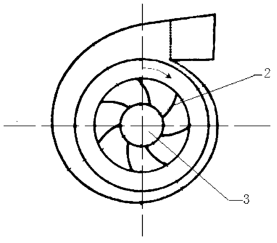
The invention discloses a centrifugal compressor with an asymmetrical vaneless diffuser and an automobile with the centrifugal compressor. The centrifugal compressor comprises a volute, a vane wheel and the vaneless diffuser. The volute comprises a first shell portion and a second shell portion, wherein the first shell portion and the second shell portion are mutually communicated, a volute chamber is defined inside the first shell portion, and a vane wheel installation space is defined inside the second shell portion. The vane wheel rotates around a rotating shaft and is arranged inside the vane wheel installation space in a rotatable mode. The width of the vaneless diffuser is distributed in a non-axis-symmetrical in the circumferential direction. The vaneless diffuser comprises a maintaining segment and a transition segment, the outlet end of the maintaining segment is communicated with the first shell portion, the inlet end of the maintaining segment is communicated with the outlet end of the transition segment, the inlet end of the transition segment is communicated with the second shell portion, the width of the maintaining segment is even at the same circumferential position in the radial direction, and the width of the transition segment is uneven at the same circumferential position in the radial direction. The centrifugal compressor with the asymmetrical vaneless diffuser can reduce the non-axis-symmetrical property of a flow field of the fluid inside the centrifugal compressor and broaden the stable working range of the centrifugal compressor.

Description

technical field [0001] The invention relates to the technical field of impeller machinery, in particular to a centrifugal compressor with an asymmetric vaneless diffuser and an automobile with the same. Background technique [0002] Compared with reciprocating compressors, impeller compressors such as centrifugal compressors have the advantages of high efficiency, light volume and weight, and stable operation, but their working conditions are limited. Under low flow conditions, large-scale flow separation occurs in the internal flow field of the centrifugal compressor, resulting in unstable operation, stalling or even surge, which directly leads to a sharp drop in compressor efficiency and pressure ratio, and severely shortens the service life, or even short-term directly damaged. [0003] The two sides of the channel of the vaneless diffuser of the centrifugal compressor adopt the shape of the fixed disc and the wheel cover. The shape is determined according to the working...

Claims


Application Information

Patent Timeline
Patent Type & Authority Applications(China)
IPC IPC(8): F04D17/10F04D29/44
Inventor 郑新前金磊林韵诸葛伟林张扬军玉木秀明川久保知己
Owner TSINGHUA UNIV
Learn More