Rotary member self-locking device and engineering machinery using same

A technology of rotating components and self-locking devices, which is applied in the direction of lifting devices, pivot connections, etc., can solve the problems of increasing chain size and installation space, irreversible, chain breakage, etc., to avoid chain size and installation space, and improve operation Safety, the effect of preventing accidental tipping

Active Publication Date: 2013-09-04
XCMG FIRE FIGHTING SAFETY EQUIP CO LTD
View PDF7 Cites 0 Cited by
  • Summary
  • Abstract
  • Description
  • Claims
  • Application Information

AI Technical Summary

Problems solved by technology

However, in the long-term frequent use process, once there are unexpected situations, such as overloading of the working bucket, stuck sprocket, vibration, and quality defects of the chain itself, which cause the chain to crack or fail, there is a hidden danger of chain breakage; When the chain breaks, the working bucket will turn down uncontrollably, directly causing the staff in the working bucket to fall, causing casualties and seriously affecting the safety performance of the product
[0004] At present, for such high-altitude vehicles with sprockets connected to the work bucket, there are no special measures to prevent the chain from breaking and tipping. Instead, the possibility of chain breakage is reduced by increasing the safety factor of the chain, which obviously cannot eliminate the possibility; In addition, this technology ca

Method used


Image

  • Rotary member self-locking device and engineering machinery using same
  • Rotary member self-locking device and engineering machinery using same
  • Rotary member self-locking device and engineering machinery using same

Examples


Embodiment Construction

[0029] The core of the present invention is to provide a self-locking device suitable for rotating components to limit the abnormal rotation of the rotating component relative to the fixed component. Through the cooperation of the components of the self-locking device, the unsafe hidden danger caused by the failure of rotation control can be completely avoided . The present embodiment will be described in detail below in conjunction with the accompanying drawings.

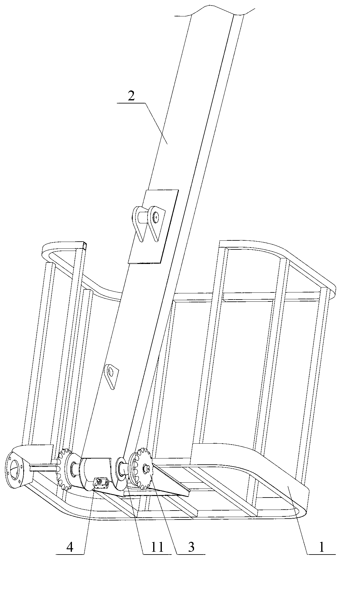
[0030] Without loss of generality, this embodiment takes the working bucket and the jib of the aerial work vehicle as the connection objects for detailed description. It should be understood that the specific connection method between the working bucket and the jib does not limit the protection scope of the present application.

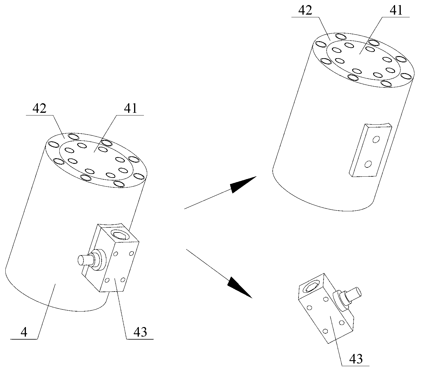
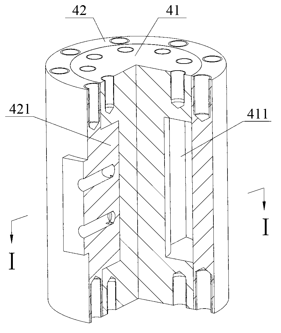
[0031] Please also see figure 1 and figure 2 ,in, figure 1 A schematic diagram showing the installation position of the rotating member self-locking device according to this embodimen...


PUM


Abstract

The invention discloses a rotary member self-locking device which comprises a cylinder rod and a cylinder barrel which are nested on the inner side and the outer side and fixedly connected with a rotary member and a fixing member respectively, wherein a first bump of the cylinder rod and the inner wall of the cylinder barrel form a first rotary pair; a second bump of the cylinder barrel and the outer surface of the cylinder rod form a second rotary pair; the first bump and the second bump are used for circumferentially dividing a medium space between the cylinder rod and the cylinder barrel into a first cavity chamber and a second cavity chamber which are relatively sealed; the first cavity chamber and the second cavity chamber are communicated with a switch valve connector opened in a normal state through a first through hole and a second through hole respectively; and a switch valve can be switched to a cut-off state according to the medium pressure of the first cavity chamber or the second cavity chamber to limit the relative movement of the cylinder rod and the cylinder barrel. The potential safety hazard caused by failure of rotation control is effectively avoided through a cooperative relationship of the members of the self-locking device, so that the safety reliability of the overall operation is guaranteed. On the basis, the invention further provides engineering machinery using the self-locking device.

Description

technical field [0001] The invention relates to the technical field of safety locking, in particular to a self-locking device for rotating components and construction machinery using the self-locking device. Background technique [0002] With the continuous development of science and technology, and the increase in the demand for aerial work in current production and life, aerial work vehicles have been widely used, which has greatly improved the safety and reliability of aerial equipment installation, maintenance and other operations. [0003] As we all know, most of the connection between the working bucket and the arm frame of the existing high-altitude operation vehicles adopts a sprocket hinge; specifically, the working bucket is installed on the sprocket shaft, and the chain pulls the sprocket to rotate when the chain moves, thereby controlling the working bucket relative to the boom. The frame rotates around the axis to a specific working position. However, in the lo...

Claims


Application Information

Patent Timeline
IPC IPC(8): F16C11/10B66F11/04
Inventor 卢良卫靳翠军
Owner XCMG FIRE FIGHTING SAFETY EQUIP CO LTD
Why Eureka
Try Eureka