
Safety valve check bench

A safety valve and calibration bench technology, which is applied in the testing of measuring devices, instruments, and mechanical parts, etc., can solve problems such as potential safety hazards, affect work efficiency, increase equipment manufacturing costs, etc., and achieve simplified equipment structure and operation. The effect of humanized operation and improved work efficiency

Inactive Publication Date: 2013-09-04
JIANGNAN UNIV
View PDF8 Cites 11 Cited by
  • Summary
  • Abstract
  • Description
  • Claims
  • Application Information

AI Technical Summary

Problems solved by technology

Even if the calibration of a small threaded safety valve requires the operator to leave the center console to clamp and adjust the safety valve on the side, it brings inconvenience to the calibration operation and affects work efficiency
The clamping of the flange safety valve adopts the clamping method of three claws. This clamping method needs to be equipped with a gasket block for safety valves of different specifications (different nominal diameters), which not only increases the manufacturing cost of the equipment, but also gives The verification operation increases the difficulty
In addition, for large-diameter safety valves, due to their heavy weight, manpower cannot move them to the clamping table, and a forklift or crane is required. It becomes very difficult. It is necessary to use a forklift to transport the safety valve to the calibration platform for calibration, and then need to use a forklift to remove the safety valve, which is time-consuming and labor-intensive and poses a safety hazard.

Method used


Image

  • Safety valve check bench
  • Safety valve check bench

Examples


Embodiment Construction

[0016] The present invention will be further described below in conjunction with specific drawings and embodiments.

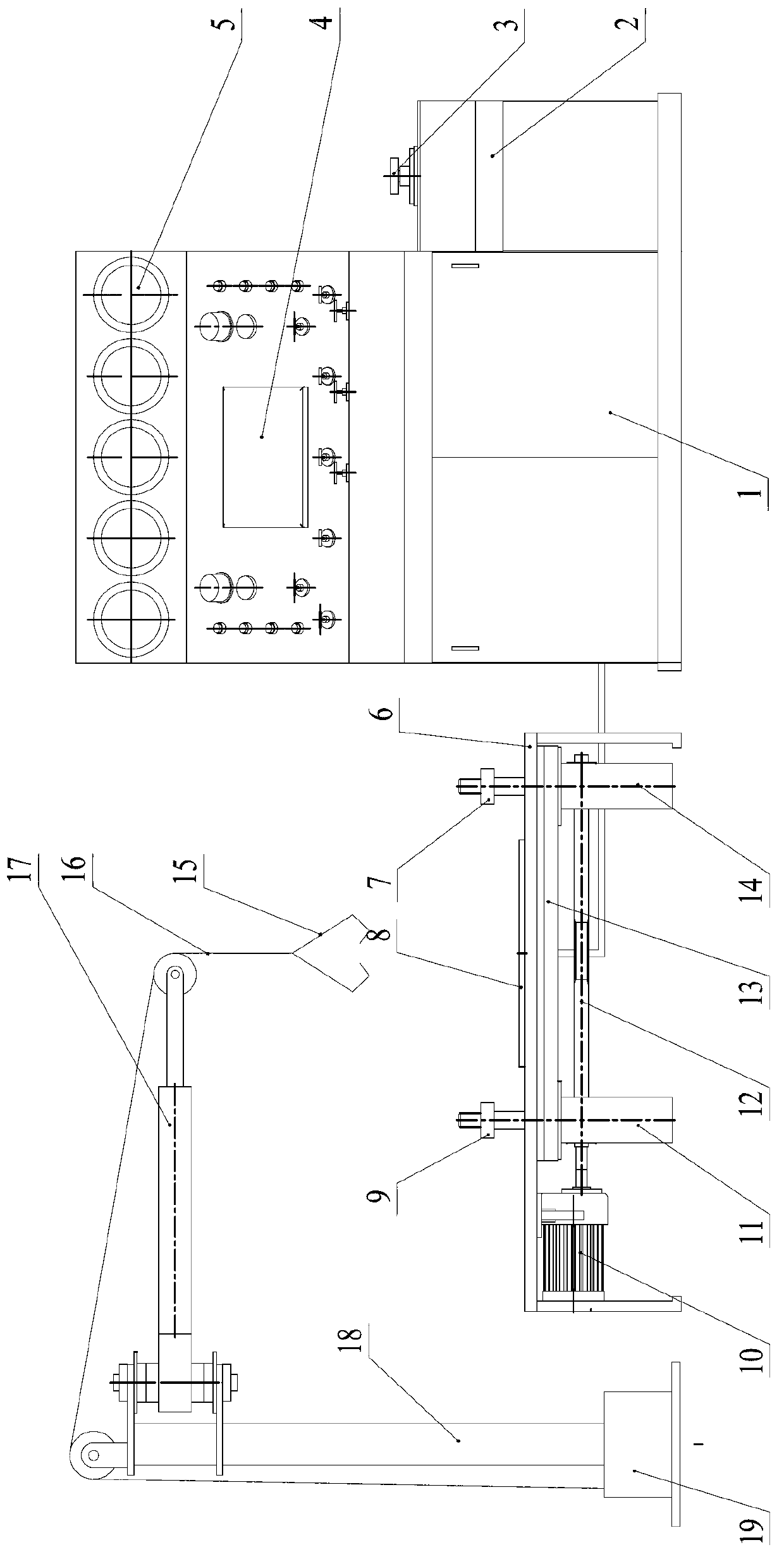
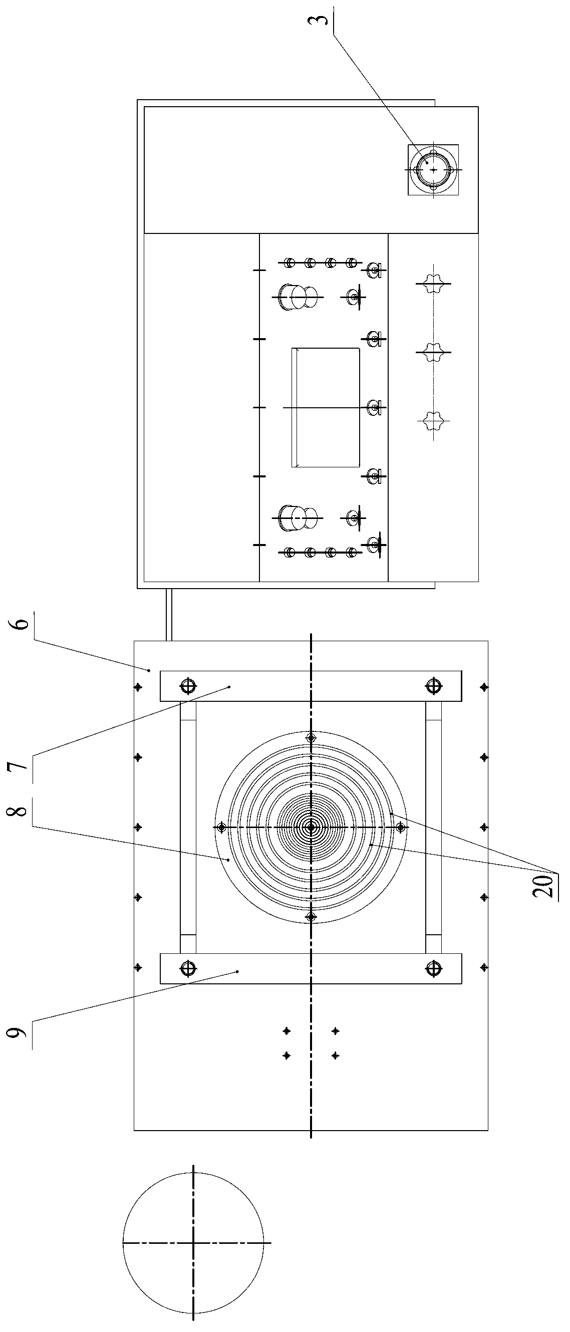
[0017] As shown in the figure: the safety valve calibration platform in the embodiment is mainly composed of three parts: the center console 1, the threaded safety valve verification device and the flange safety valve verification device. The threaded safety valve verification device and the method The blue safety valve calibration devices are arranged on the left and right sides of the center console 1 respectively.

[0018] like figure 1 , figure 2 As shown, the threaded safety valve verification device is mainly composed of a threaded base 2 and a threaded safety valve joint 3, the threaded safety valve joint 3 is installed on the threaded base 2 in a detachable and replaceable form, and the threaded safety valve joint 3 is used for It is suitable for connecting threaded safety valves that need to be verified; by replacing threaded safety valve connectors...


PUM


Abstract

The invention relates to a safety valve check bench. A threaded safety valve check unit and a flanged safety valve check unit are respectively arranged by the left side and right side of a central console, the threaded safety valve check unit comprises a threaded base and a threaded safety valve connector, and the threaded safety valve connector is detachably mounted on the threaded base, and is used for connection with a threaded safety valve; in the flanged safety valve check unit, a sealed underpan is arranged on the top of a flanged safety valve-clamping table, and is provided with O-shaped rings which can be tightly matched with the inlet flange of a flanged safety valve for sealing; a first clamping plate and a second clamping plate are respectively arranged on both sides of the sealed underpan, and can be driven by a clamping plate-driving mechanism to transversely get close to each other or get away from each other at the same time and vertically goes up or down at the same time in order to hold the inlet flange of the flanged safety valve. The safety valve check bench is convenient to use, is more complete in functions, and can decrease the intensity of the work of operators and increase working efficiency.

Description

technical field [0001] The invention relates to safety valve calibration equipment, in particular to a safety valve calibration platform for off-line calibration of safety valves. Background technique [0002] Safety valve off-line calibration refers to removing the safety valve from the protected equipment and performing calibration at the safety valve calibration station. The safety valve calibration bench is the main equipment for off-line calibration, which is used for opening pressure adjustment and sealing performance test of safety valves. [0003] When the existing safety valve calibration platform is used to calibrate the safety valve, the threaded safety valve (referring to: the air inlet of the safety valve and the pipeline of the protected equipment adopts a threaded connection method) and the flange safety valve (referring to: the safety valve The air inlet and the pipeline of the protected equipment are connected by flange) and both use the same clamping stati...

Claims


Application Information

Patent Timeline
IPC IPC(8): G01M13/00
Inventor 朱海清张小林钱瑛王海龙
Owner JIANGNAN UNIV
Learn More