Buzzer drive circuit

A technology for driving circuits and buzzers, applied in transducer circuits, sensors, electrical components, etc., can solve the problems affecting the sound quality and volume of the buzzer, the voltage bias of the buzzer, and the bulky volume, and achieve good sound quality. , Avoid DC voltage bias, the effect of small installation volume

Inactive Publication Date: 2013-09-04
WUXI ECOVI TECH
View PDF5 Cites 5 Cited by
  • Summary
  • Abstract
  • Description
  • Claims
  • Application Information

AI Technical Summary

Problems solved by technology

[0002] The existing buzzer driving circuit is generally driven by a DC pulse signal. When the music buzzer needs to be realized, the electrolytic capacitor is discharged to realize the switching from high to low or from low to high between each syllable. The buzzer driving method adopts Driven by a DC pulse signal, the buzzer can only vibrate in one dir

Method used


Image

  • Buzzer drive circuit
  • Buzzer drive circuit

Examples


Embodiment Construction

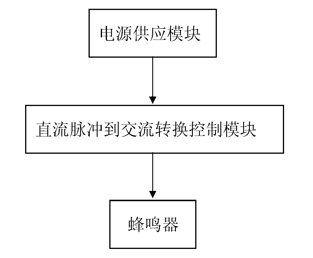
[0024] Such as figure 1 , 2 The buzzer drive circuit shown includes an electrically connected power supply module and a control module, and the control module is connected to the buzzer H to drive the buzzer H, wherein: the control module is DC The pulse-to-AC conversion control module makes the driving voltage at both ends of the buzzer H become an AC voltage with the same control frequency and alternating directions, so that the buzzer of the buzzer H vibrates back and forth in two directions;

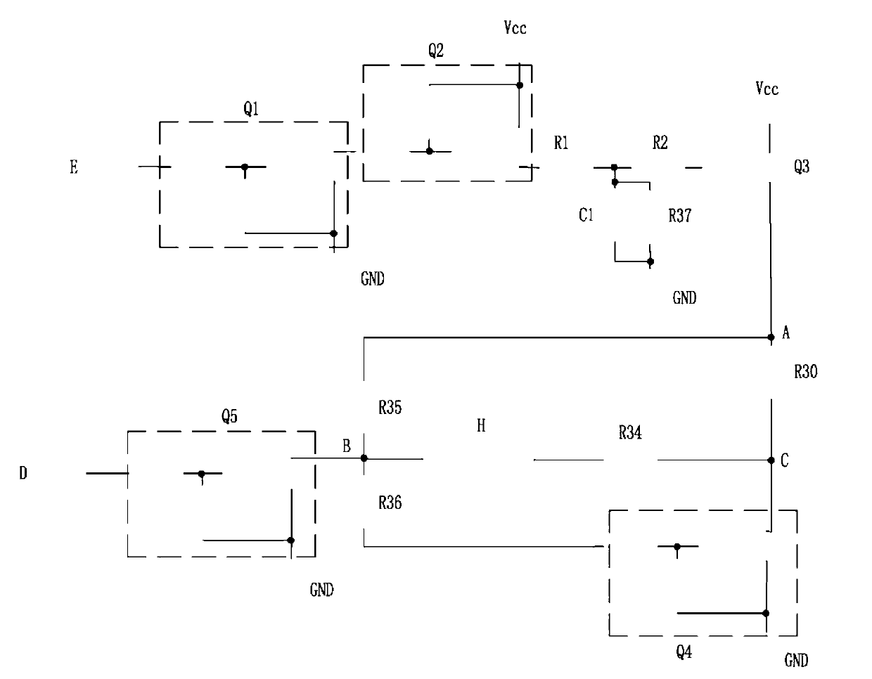
[0025] The DC pulse-to-AC conversion control module includes a DC pulse signal output terminal D, a fifth transistor Q5, and a fourth transistor Q4. The DC pulse signal output terminal D outputs a DC pulse signal with a certain period, so The fifth triode Q5 and the fourth triode Q4 described above respectively realize their own periodic conduction / cutoff or cutoff / conduction actions under the action of the DC pulse signal, and then realize the driving voltage at both ends of the bu...


PUM


Abstract

The invention relates to a buzzer drive circuit, comprising a power supply module and a control module which are electrically connected with each other, wherein the control module is connected with a buzzer H to drive the buzzer H, the control module is a conversion control module capable of converting direct current pulse to alternating current pulse, so that the drive voltages at the two ends of the buzzer H become alternating voltages with the same control frequencies and alternating directions, a buzzing piece of the buzzer H is further enabled to vibrate back and forth in two directions, and the buzzer is accordingly enabled to obtain greater volume; as the drive voltages of the buzzer are alternating voltages in alternating directions, the direct voltage offset problem in the prior art is avoided, and the buzzer is further enabled to obtain sound producing effects such as better sound quality, volume and the like.

Description

technical field [0001] The invention relates to a buzzer driving circuit. Background technique [0002] The existing buzzer driving circuit is generally driven by a DC pulse signal. When it is necessary to realize the music buzzer, the electrolytic capacitor is discharged to realize the switching from high to low or from low to high between each syllable. The buzzer driving method adopts Driven by a DC pulse signal, the buzzer can only vibrate in one direction, resulting in low volume; due to the existence of electrolytic capacitors, there will be a certain voltage bias when the buzzer is working, which will affect the sound quality and volume of the buzzer; Moreover, because the electrolytic capacitor discharge method is used to realize the slow alternation of the volume, it is not only bulky but also costly. Contents of the invention [0003] The technical problem to be solved by the present invention is to provide a buzzer drive circuit, the buzzer piece of the buzzer ...

Claims


Application Information

Patent Timeline
IPC IPC(8): H04R3/00
Inventor 陈耀华王超刘猛
Owner WUXI ECOVI TECH
Why Eureka
Try Eureka