
Multi-stage supercharging device

A technology of supercharging device and supercharger, which is applied in gas turbine device, charging system, internal combustion piston engine, etc., can solve the problem that the flow resistance of the exhaust flow path increases, the sealing performance decreases, and the pressure loss of the exhaust gas flow increases, etc. problems, to achieve the effect of improving the supercharging efficiency and improving the sealing performance

Active Publication Date: 2013-09-04
ISUZU MOTORS LTD
View PDF11 Cites 11 Cited by
  • Summary
  • Abstract
  • Description
  • Claims
  • Application Information

AI Technical Summary

Problems solved by technology

In addition, the shape of the exhaust pipe as a whole is complicated, and the flow resistance of the exhaust flow path increases, so the pressure loss of the exhaust flow may increase.
In addition, due to the weight of the turbocharger, the sealing performance of the connecting part (pipe fastening part) between the two turbochargers may also be reduced.

Method used


Image

  • Multi-stage supercharging device
  • Multi-stage supercharging device
  • Multi-stage supercharging device

Examples


Embodiment Construction

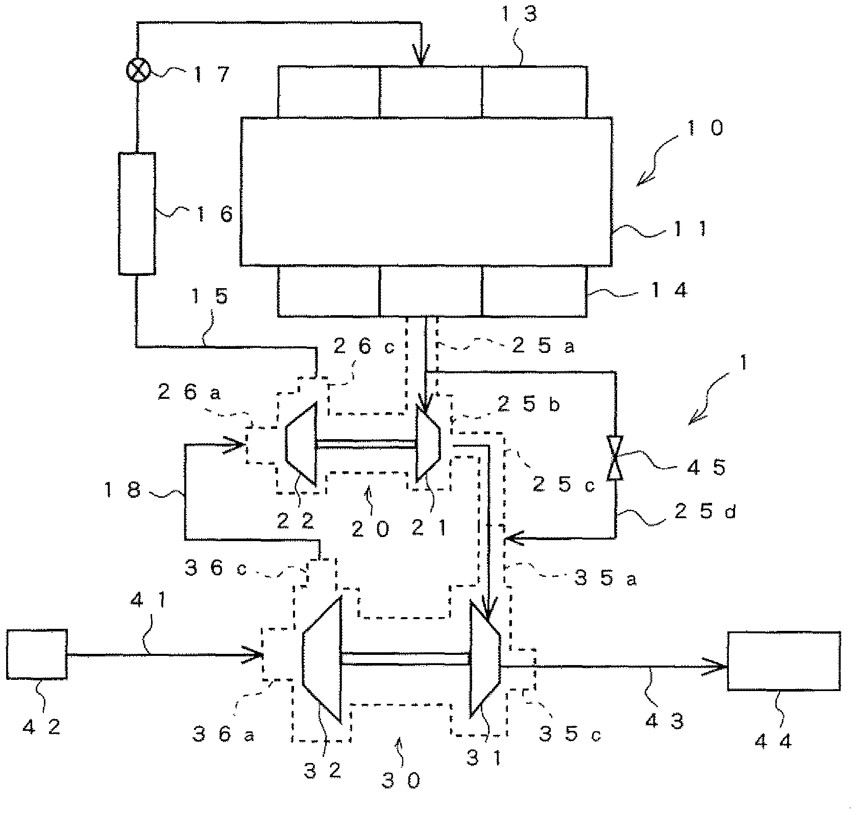
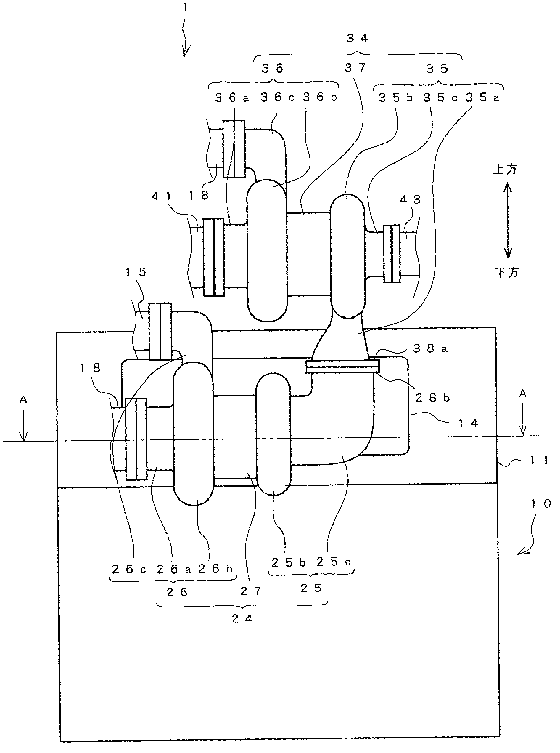
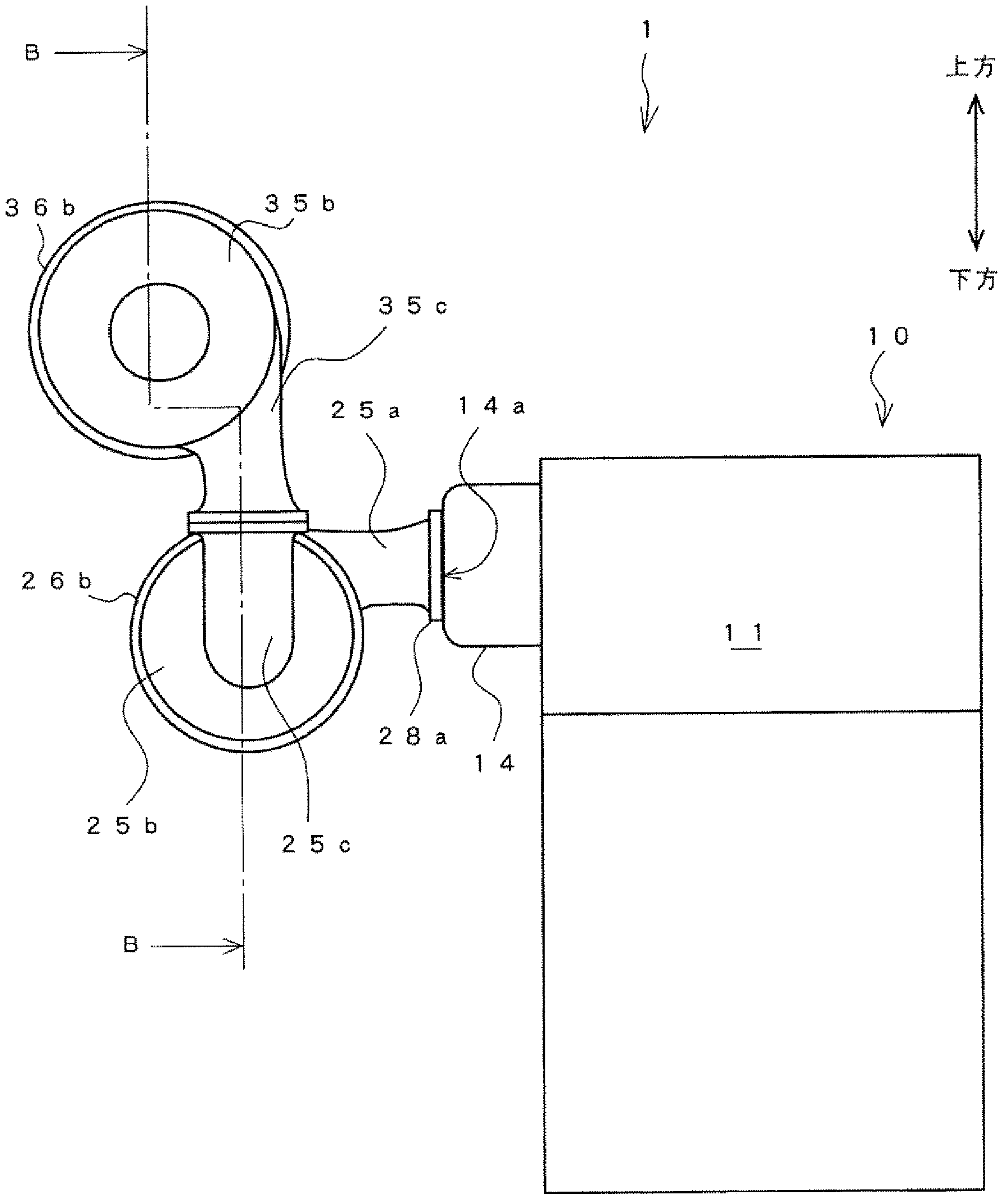
[0024] Below, according to Figure 1~5 A multistage booster device according to one embodiment of the present invention will be described. The same reference numerals are assigned to the same components, and their names and functions are also the same. Therefore, detailed description thereof will not be repeated.

[0025] A multi-stage supercharging device 1 according to an embodiment of the present invention is as figure 1 As shown, a diesel engine (hereinafter simply referred to as an engine) 10 mounted on a vehicle is provided in parallel, and has a high-pressure stage turbocharger 20 and a low-pressure stage turbocharger 30 having a larger capacity than the high-pressure stage turbocharger 20 . In addition, the high-pressure-stage turbocharger 20 of the present embodiment corresponds to the first supercharger of the present invention. In addition, the low-pressure stage turbocharger 30 of the present embodiment corresponds to the second supercharger of the present inven...


PUM


Abstract

A multi-stage supercharging device configured in such a manner that the sealing properties of the portion at which a high-pressure stage turbocharger and a low-pressure stage turbocharger are connected is improved. A multi-stage supercharging device (1) has a first supercharger (20) and a second supercharger (30). The first supercharger (20) is provided with a first turbine housing section (25b), a first exhaust gas inlet section (25a), and a first exhaust gas outlet section (25c) which is extended in the direction of the axis of the first turbine (21) from the first turbine housing section (25b) and is bent upward. The second supercharger (30) is provided with a second turbine (31), a second turbine housing section (35b), and a second exhaust gas inlet section (35a) which is directly connected to the first exhaust gas outlet section (25c) and which connects the first exhaust gas outlet section (25c) and the second turbine housing section (35b). The opening of the second exhaust gas inlet section (35a) is mounted on the opening of the first exhaust gas outlet section (25c) to cause the second supercharger (30) to be supported by the first supercharger (20).

Description

technical field [0001] The present invention relates to a multi-stage supercharging device, in particular to a multi-stage supercharging device having a first supercharger and a second supercharger driven by the exhaust gas of an engine. Background technique [0002] As a system for efficiently recovering exhaust energy of an engine, a two-stage supercharging system (multi-stage supercharging device) is known. Generally, this two-stage supercharging system is a high-pressure stage turbocharger (first supercharger) arranged in series in the exhaust passage from the upstream side of the exhaust gas flow, and a high-pressure stage turbocharger and a low-pressure stage turbocharger. The low-pressure stage turbine of the compressor (second supercharger). Further, on the intake passage side, a low-pressure stage compressor of the low-pressure stage turbocharger and a high-pressure stage compressor of the high-pressure stage turbocharger are arranged in series in this order from t...

Claims


Application Information

Patent Timeline
Patent Type & Authority Applications(China)
IPC IPC(8): F02B37/013F02B37/00
CPCF02B37/004F02B37/013F02B37/18F02C6/12F02B37/183F02M26/00Y02T10/12
Inventor 仓田伊织宇野忍大石和贵
Owner ISUZU MOTORS LTD
Learn More