Drilling fixture

A drilling jig and drill sleeve technology, applied in the field of machining, can solve the problems of easy shaking, unfavorable staff safety, affecting processing accuracy, etc., and achieves the effects of strong flexibility, stable drilling quality, and reliable workpiece fixation.

Active Publication Date: 2013-09-11
SUZHOU CHIEN SHIUNG INST OF TECH
View PDF5 Cites 15 Cited by
  • Summary
  • Abstract
  • Description
  • Claims
  • Application Information

AI Technical Summary

Problems solved by technology

[0002] In the drilling process of mechanical processing, the commonly used methods are hand-held and fixture, but there are many problems in both hand-held and fixture. Hand-held machining is prone to shaking due to the influence of mechanical force during the machining process. It affects the machining accuracy, and there are safety hazards in

Method used


Image

  • Drilling fixture
  • Drilling fixture
  • Drilling fixture

Examples


Embodiment Construction

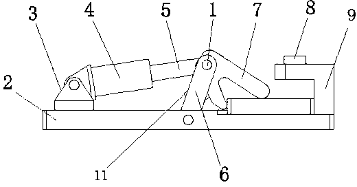
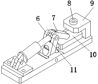
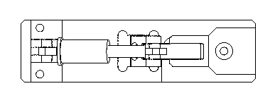
[0015] Such as Figure 1-3 The shown drilling jig includes a base 2, a positioning plate 9 and a drill sleeve 8. The positioning plate 9 includes a top plate and a support plate connected to one end of the top plate. The top plate and the support plate are perpendicular to each other, and the support plate is movably connected to the base 2. A vertical groove structure is formed between the positioning plate 9 and the base 2; the drill sleeve 8 passes through the top plate of the positioning plate 9 and is arranged on the top plate.

[0016] Before the workpiece is installed, the spring 11 can balance the gravitational effect of the pressing block 7, so as to prevent the excessive drooping angle of the pressing block 7 from affecting the installation of the workpiece; the processed part 10 is placed in the groove of the base 2, and the cylinder piston 5 is stretched out to drive the connecting rod 6 and the briquetting block 7 rotate, and the two legs of the briquetting block ...


PUM


Abstract

The invention discloses a drilling fixture which comprises a base, a positioning plate and a drill bushing. The positioning plate comprises a top plate and a supporting plate connected with one end of the top plate, the top plate is perpendicular to the supporting plate which is movably connected to the base, a vertical groove structure is formed between the positioning plate and the base, and the drill bushing penetrates the top plate and is arranged on the same. The drilling fixture has high flexibility, and processing of different parts can be realized by the same fixture. Since workpieces can be clamped by force from both the top surface and the side surface, the workpieces can be fixed firmly, and drilling quality is stable. Besides, the drilling fixture has a pneumatic locking effect, and accordingly is convenient and reliable.

Description

technical field [0001] The invention relates to the field of machining, in particular to a drilling jig. Background technique [0002] In the drilling process of mechanical processing, the commonly used methods are hand-held and fixture, but there are many problems in both hand-held and fixture. Hand-held machining is prone to shaking due to the influence of mechanical force during the machining process. It affects the machining accuracy, and there are safety hazards in hand-held machining, which is not conducive to the safety of the staff. In addition, the work efficiency of hand-held machining cannot be guaranteed; the problem with jig-type machining is that it is difficult for a jig to adapt to workpieces of different shapes Drilling requirements, and the reliability of the workpiece clamping device is not enough. Contents of the invention [0003] Purpose of the invention: The technical problem to be solved by the present invention is to provide a drilling jig. [00...

Claims


Application Information

Patent Timeline
IPC IPC(8): B23Q3/08
Inventor 郑勇许红伍倪红海王洪磊张福周
Owner SUZHOU CHIEN SHIUNG INST OF TECH
Why Eureka
Try Eureka