
Wind turbine blade with split winglet at apex

A wind turbine blade and tip technology, applied in the field of wind power generation, can solve the problems of dispersing the intensity of blade tip vortex, weakening the induced influence of blade tip vortex, etc.

Inactive Publication Date: 2013-09-11
NANJING UNIV OF AERONAUTICS & ASTRONAUTICS
View PDF5 Cites 9 Cited by
  • Summary
  • Abstract
  • Description
  • Claims
  • Application Information

AI Technical Summary

Problems solved by technology

This design is simple, but it cannot effectively disperse the intensity of the tip vortex and weaken the induced influence of the tip vortex, so it has limited effect on improving the aerodynamic performance of the wind turbine or suppressing the influence of the tip vortex in the wake.

Method used


Image

  • Wind turbine blade with split winglet at apex
  • Wind turbine blade with split winglet at apex
  • Wind turbine blade with split winglet at apex

Examples


Embodiment 1

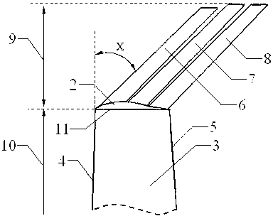
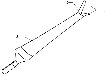
[0028] Figure 1 ~ Figure 3 For utilizing the shape of embodiment one blade of the present invention. The length of the main body of the blade is 4.5 meters, the airfoil of the main blade is S809 airfoil, the relative thickness of the airfoil is 21%, the chord length of the tip 11 of the main blade is 0.21 meters, and the projected length 9 of the winglet 1 on the centerline of the main blade is 0.225 rice.

[0029] refer to figure 1 , is the overall perspective view of Embodiment 1. The split winglet is composed of a winglet 1 and a root connecting section 2 which connects the winglet 1 with the main blade 3 .

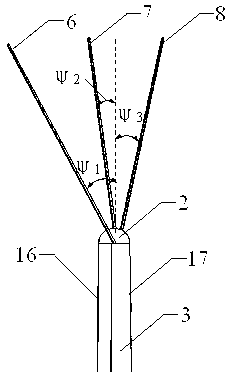
[0030] refer to figure 2 , is the front view of Embodiment 1. The winglet 1 is composed of three sub-wings, from the leading edge 4 to the trailing edge 5 are the front sub-wing 6 , the middle sub-wing 7 and the rear sub-wing 8 . The projection length 9 of the winglet 1 on the centerline of the main blade is 5% of the length 10 of the main blade. The three sub...

Embodiment 2

[0033] Figure 4 ~ Figure 6 For utilizing the shape of embodiment two blades of the present invention. The length of the main blade is 4.5 meters, the tip of the main blade is S809 airfoil, the relative thickness of the airfoil is 21%, the chord length of the tip 11 of the main blade is 0.21 meters, and the projected length 9 of the winglet 1 on the centerline of the main blade is 0.675 rice.

[0034] refer to Figure 4 , is the overall perspective view of the second embodiment. The split winglet is composed of a winglet 1 and a root connecting section 2 which connects the winglet 1 with the main blade 3 .

[0035] refer to Figure 5 , is the front view of the second embodiment. Winglet 1 is made up of two sub-wings, and from leading edge 4 to trailing edge 5 is successively front sub-wing 6 and rear sub-wing 8 . The projection length 9 of the winglet 1 on the centerline of the main blade is 15% of the length 10 of the main blade. The shape of the two sub-wings is the s...


PUM


Abstract

The invention relates to a wind turbine blade with a split winglet at the apex, which belongs to the field of wind power generation and comprises a winglet (1), a root connecting part (2) and a main blade (3), wherein the winglet (1) is composed of n sub wings, n is 2 or 3, and all the sub wings are trapezoid-shaped with the same taper and sweepback (12), the n sub wings are provided with different anhedrals; the root connecting part (2) extends out of a main blade apex (11) and is an irregular sphere in shape by taking the wing section of the main blade apex as the standard; the irregular sphere wraps the main blade apex (11) and is connected with the sub wings. According to the invention, the spanwise flow of the blade apex can be reduced, the vortice density of the blade apex without the winglet is dispersed, the induced resistance exerted by the blade apex vortex to the blade is weakened, and the purposes of improving the aerodynamic performance of the wind turbine and restraining the effect of the blade vortex in wake flow are realized, so that the aerodynamic performance is brought into play to the greatest degree.

Description

technical field [0001] The invention relates to a wind turbine blade with split winglets at the tip, which belongs to the field of wind power generation. Background technique [0002] The strategic position of wind energy as an important part of future energy supply has been recognized by countries all over the world. my country's wind power development has been advancing steadily, especially during the "Eleventh Five-Year Plan" period, it has experienced explosive growth. At present, my country's cumulative installed capacity of wind power has leapt to the first place in the world. Under this trend, the development of high-performance wind turbine blades is of great significance to the stable development of energy in the future. [0003] There are many ways to improve the performance of wind turbine blades, such as increasing the wind capture area of ​​the wind rotor, increasing the chord length of the blades, and adopting flow control. The modification of the first two w...

Claims


Application Information

Patent Timeline
IPC IPC(8): F03D11/00
Inventor 张震宇许波峰王同光王珑罗源
Owner NANJING UNIV OF AERONAUTICS & ASTRONAUTICS
Learn More