Electrowetting display device

An electrowetting display and component technology, applied in optical components, optics, instruments, etc., can solve problems such as complex processes and lower aperture ratios

Active Publication Date: 2013-09-11
IND TECH RES INST
View PDF3 Cites 22 Cited by
  • Summary
  • Abstract
  • Description
  • Claims
  • Application Information

AI Technical Summary

Problems solved by technology

But the former design reduces the aperture ratio, while the latter has a more complicated process

Method used


Image

  • Electrowetting display device
  • Electrowetting display device
  • Electrowetting display device

Examples


Embodiment Construction

[0035] Hereinafter, each embodiment is described in detail and examples accompanied by drawings are used as a reference basis of the present invention. In the drawings or descriptions in the specification, similar or identical parts all use the same figure numbers. And in the drawings, the shapes or thicknesses of the embodiments may be enlarged, and marked for simplicity or convenience. Furthermore, the parts of each element in the drawings will be described separately. It should be noted that the elements not shown or described in the drawings are forms known to those of ordinary skill in the art. In addition, specific embodiments It is only used to disclose the specific method used in the present invention, and it is not intended to limit the present invention.

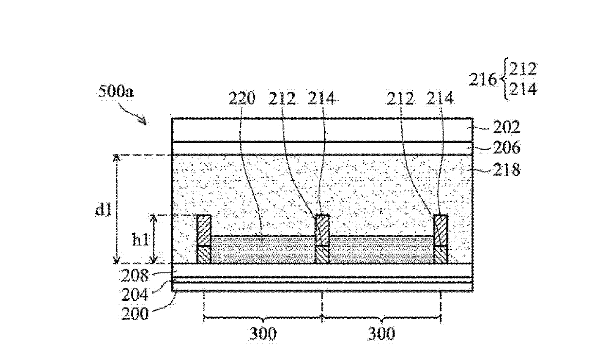
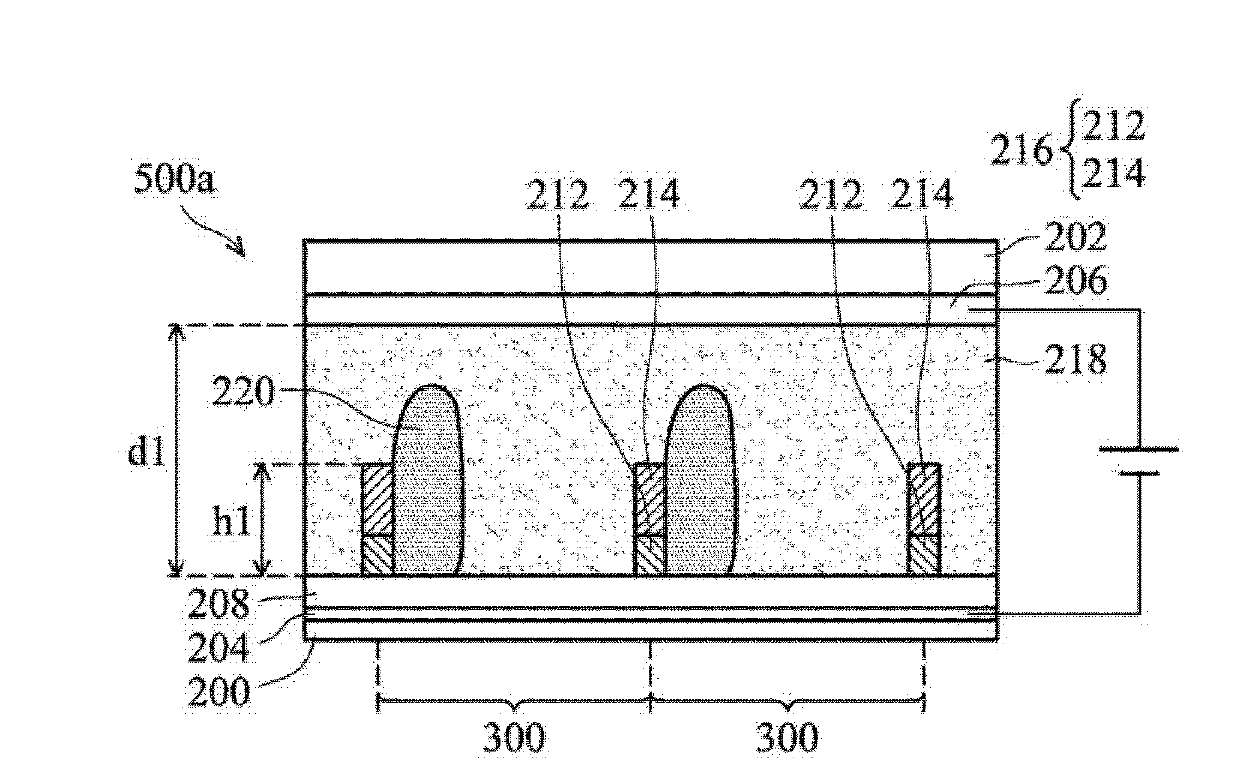
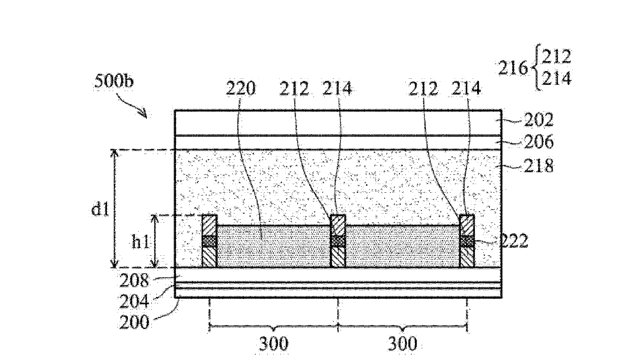
[0036] An embodiment of the present invention provides an electrowetting display element, which can control the filling amount of ink in the dip coating process by adjusting the hydrophilicity of the double-layer ...


PUM


Abstract

The disclosure provides an electrowetting display device. The electrowetting display device includes a first substrate and a second substrate disposed to each other. A first electrode layer may dispose on the first substrate. A second electrode layer may dispose on the second substrate. A hydrophobic dielectric layer is disposed on the first electrode layer. A first pixel rib is disposed on the first substrate. A second pixel rib is disposed on the first pixel rib. A water contact angle of the second pixel rib may be larger than that of the first pixel rib. A first liquid and a second liquid may be disposed in between the first substrate and the second substrate. The electrowetting display device can prevent the problem of an existing electrowetting display device that the second liquid with large injection amount will contract to generate overflow, can also improve uniformity after panel drive and reliability of panel operation without affecting contrast ratio of the electrowetting display device.

Description

technical field [0001] The invention relates to an electrowetting display element, in particular to a pixel blocking wall of an electrowetting display. Background technique [0002] With the rapid development of optoelectronic technology, various displays are also flourishing. Electro-wetting display (EWD) has been highly valued due to its advantages of high contrast ratio, high response time, low power consumption and high resolution. [0003] The electrowetting display was first developed by Liquavista Company. This display includes non-polar oil droplets, polar aqueous solution, hydrophobic layer and hydrophilic barrier (rib). The polar oil droplets are separated by a hydrophilic barrier, and the polar aqueous solution is above the non-polar oil droplets. The principle of operation is as follows: When no voltage is applied to the display, non-polar oil droplets spread out on top of the hydrophobic layer, thus taking on the color of the oil droplets. When a voltage is a...

Claims


Application Information

Patent Timeline
Patent Type & Authority Applications(China)
IPC IPC(8): G02B26/02
CPCG02B26/005
Inventor 郭书玮古昀生郑惟元郑佩佩
Owner IND TECH RES INST
Why Eureka
Try Eureka