Acceleration switch

A technology of acceleration switch and gravity block, which is applied in the field of sensors, can solve problems such as system inoperability, and achieve the effect of increasing selectivity and strengthening stability

Active Publication Date: 2013-09-11
安徽省湘凡科技有限公司
View PDF4 Cites 11 Cited by
  • Summary
  • Abstract
  • Description
  • Claims
  • Application Information

AI Technical Summary

Problems solved by technology

However, the disadvantage of this structure is that the movable contact and the static contact will separate immediately after contact. If the switch does not trigger the switch due to contact problems at the moment of contact between the movable and static contacts, and the acceleration decreases after a certain period of time, so that the generated Inertial displacement cannot make the dynamic and static contacts contact, in other words, the switch has only one chance to trigger, then the switch will not trigger again, causing the whole system to fail to work

Method used


Image

  • Acceleration switch
  • Acceleration switch
  • Acceleration switch

Examples


Embodiment Construction

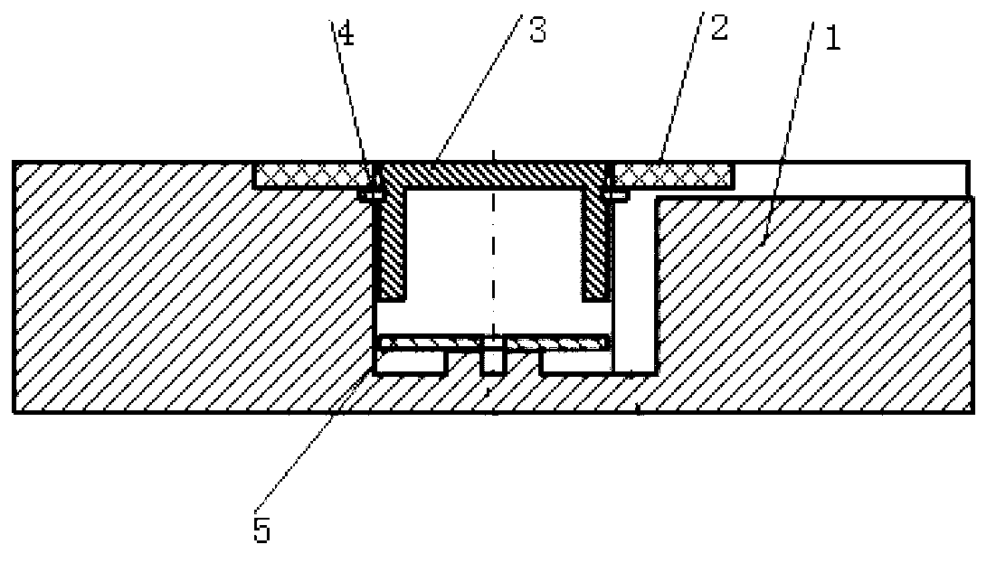
[0026] Such as figure 1 As shown, an acceleration switch of the present invention includes a housing 1, a cover plate 2, a gravity block 3, an elastic clamping device 4, and a reed 5; Distribution, wherein the gravity block 3 is located above the reed 5; the elastic clamping device 4 is arranged inside the shell 1 and clamps the gravity block 3, and its elastic expansion and contraction direction is perpendicular to the gravity direction; the cover plate 2 is fixed on the shell 1, the middle part of the cover plate 2 is provided with a through hole, the through hole is located above the gravity block 3; the reed 5 is fixed on the bottom inner wall of the shell 1, and the gravity block 3 and the reed 5 are respectively connected to the switch of the poles.

[0027] Such as figure 2 As shown, the cover plate 2 is fixed on the top of the housing 1 by means of nuts or pasting, and the middle part of the cover plate 2 is provided with a through hole, which is located above the g...


PUM


Abstract

The invention discloses an acceleration switch which comprises a shell (1), a cover plate (2), a gravity block (3), an elastic clamping device (4) and a reed (5). The gravity block (3) and the reed (5) are disposed in the shell (1) and distributed in the gravity direction. The gravity block (3) is located above the reed (5). The elastic clamping device (4) is disposed in the shell (1) and clamps the gravity block (3). The elastic telescoping direction of the elastic clamping device (4) is perpendicular to the gravity direction. The cover plate (2) is fixed at the top end of the shell (1). A through hole is formed in the middle of the cover plate (2). The through hole is located above the gravity block (3). The reed (5) is fixed on the bottom inner wall of the shell (1). The gravity block (3) and the reed (5) are respectively connected to two electrodes of the switch. By the structure, the switch can be triggered all the time.

Description

technical field [0001] The invention belongs to the field of sensors, and more specifically relates to an acceleration switch. Background technique [0002] A switch is an electronic component used to connect, disconnect or convert a circuit to control the operation or stop of an electrical device. According to different structures and uses, switches have different classification methods. Mechanical switches are widely used in electronic devices and equipment. [0003] The mechanical acceleration switch uses acceleration to make the two poles of the switch close by relying on substantial contact to control the switch. It does not need a switching power supply. It can save space in some conditions with relatively high space requirements, and can meet long-term use. Since the mechanical acceleration switch completes the conduction of the switch by the substantial contact between the two poles of the switch, whether the two poles of the switch are in good contact determines w...

Claims


Application Information

Patent Timeline
Patent Type & Authority Applications(China)
IPC IPC(8): H01H35/14
Inventor 陈超任金华
Owner 安徽省湘凡科技有限公司
Why Eureka
Try Eureka