
Tie

A cable tie and band-shaped technology, applied in the field of cable tie structure design, can solve the problems of inconvenience in use, hinder the next use of ligature, easy loss of cable ties, cable ties and rubber bands, etc., and achieve the effect of preventing the loss of cable ties

Inactive Publication Date: 2013-09-18
苏州苏越电气有限公司
View PDF8 Cites 8 Cited by
  • Summary
  • Abstract
  • Description
  • Claims
  • Application Information

AI Technical Summary

Problems solved by technology

[0002] Existing wired devices, such as mice, earphones, chargers, etc. all have long cables, which are easily tangled into a mess when carried and stored, which is quite inconvenient to use
When these electrical appliances with cables leave the factory, their single cables are repeatedly folded to form a bundle of cables, and then tied on the bundle of cables with cable ties, cables or rubber bands. Disassemble the cable ties, cables or rubber bands, so the cable ties, cables and rubber bands are easily lost, which hinders the use of the next ligation

Method used


Image

  • Tie
  • Tie
  • Tie

Examples


Embodiment 2)

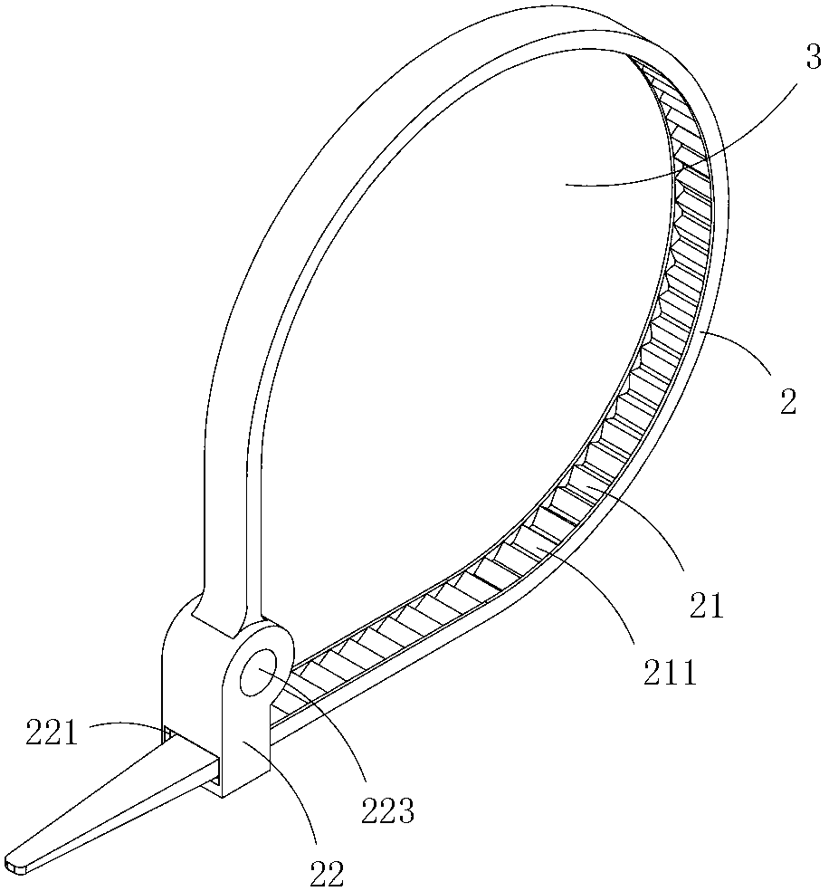
[0022] Image 6 with Figure 7 A second specific embodiment of the present invention is shown, in which, Image 6 Is a schematic diagram of a three-dimensional structure of the second structure of the present invention; Figure 7 Yes Image 6 A schematic structural diagram of the cable tie after forming a loop.

[0023] This embodiment is basically the same as Embodiment 1, but the difference is that the locking head is provided with a V-shaped guide channel 224 that communicates the wire clamping hole with the outside, and the V-shaped guide channel is located in the tie ring.

[0024] When this embodiment is in use, a V-shaped guide channel can be used to directly insert a single cable into the clamping hole 223, and since the shape of the guide channel is V-shaped, by adjusting the width of the narrowest part of the V-shaped guide channel, for example, Smaller than the outer diameter of a single cable, it can also effectively prevent the cable from falling off the clamping hole. ...

Embodiment 3)

[0026] Figure 8 It is a schematic structural diagram of the third structure of the present invention, and shows a specific embodiment of the present invention.

[0027] This embodiment is basically the same as Embodiment 1, but the difference is that: the locking head is also provided with an auxiliary belt 5 and an anti-drop hole 6 matched with the auxiliary belt; the auxiliary belt is provided with wedge-shaped teeth 51, and the anti-drop hole is provided There are anti-dropping teeth 61 matched with the wedge-shaped teeth; the auxiliary belt passes through the anti-dropping holes and is enclosed to form a thread clamping hole 223, and the thread clamping hole is located in the tie ring.

[0028] When this embodiment is in use, a single cable is clamped by the wire clamping hole 223. Since the wire clamping hole is formed by enclosing the auxiliary belt, it is more convenient to use and can be applied to various cables of different thicknesses.


PUM


Abstract

The invention discloses a tie which comprises a tie body and a locking head integrally made together with the tie body; a wedge tooth area is arranged on the tie body; a fastening hole is formed in the locking head; a positioning lock tongue matched with the wedge tooth area is arranged in the fastening hole; after the tie body passes through the fastening hole of the locking head, a tying ring is formed; a line clamping hole in the extension direction perpendicular to the tie body is also formed in the locking head. The tie has the advantage of convenience in use and can tie up cables tidily.

Description

Technical field [0001] The invention belongs to the technical field of cable tie structure design, and specifically relates to a cable tie. Background technique [0002] Existing wired devices, such as mice, earphones, chargers, etc., have long cables, which are easily entangled in a mess when carrying and storing, which is quite inconvenient to use. When these electrical appliances with cables leave the factory, a single cable is repeatedly folded to form a bundled cable, and then it is tied to the bundled cable with a tie, cable tie or rubber band. Disassemble the cable tie, cable tie or rubber band, so the cable tie, cable tie and rubber band are easy to lose, hindering the next banding use. Summary of the invention [0003] The object of the present invention is to provide a cable tie for bundling cables that is convenient to use and prevents loss. [0004] The technical solution for realizing the present invention is: a cable tie comprising a belt-shaped body and a lo...

Claims


Application Information

Patent Timeline
Patent Type & Authority Applications(China)
IPC IPC(8): B65D63/12
Inventor 黄海林
Owner 苏州苏越电气有限公司
Learn More