
Redundant output device

An output device and redundant technology, applied in the direction of comprehensive factory control, comprehensive factory control, electrical program control, etc., can solve the problems of large current impact of the instrument and shorten the service life of the instrument at the control site, so as to reduce the current impact and prolong the life of the instrument. The effect of service life

Active Publication Date: 2013-09-18
HANGZHOU HOLLYSYS AUTOMATION
View PDF3 Cites 9 Cited by
  • Summary
  • Abstract
  • Description
  • Claims
  • Application Information

AI Technical Summary

Problems solved by technology

[0004] Therefore, in the process of redundancy switchover, the instruments in the control field will experience the process of current signals from being present to non-existing and then back to being present, which will cause the instruments in the control field to bear a greater current impact, thus shortening the The service life of the instrument

Method used


Image

  • Redundant output device
  • Redundant output device
  • Redundant output device

Examples


Embodiment Construction

[0047] The following will clearly and completely describe the technical solutions in the embodiments of the present invention in conjunction with the accompanying drawings in the embodiments of the present invention. Obviously, the described embodiments are only some of the embodiments of this embodiment, not all of them. Based on the embodiments of the present invention, all other embodiments obtained by persons of ordinary skill in the art without making creative efforts belong to the scope of protection of the present invention.

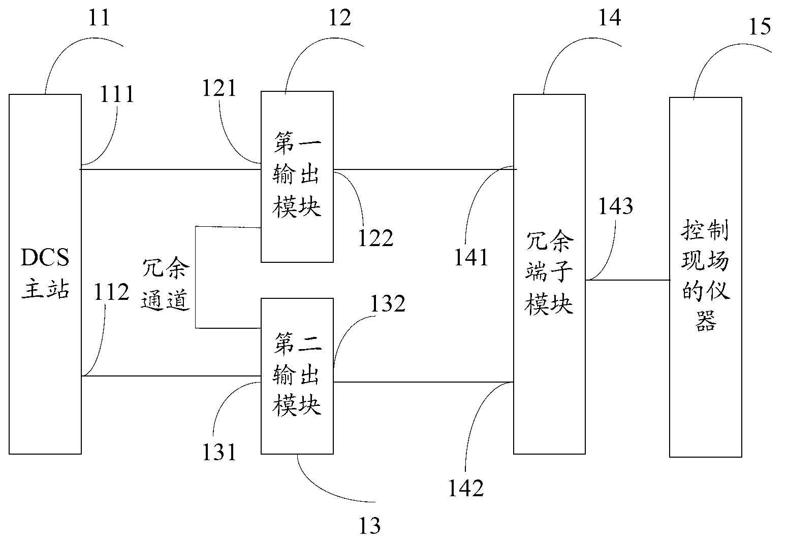
[0048] The invention discloses a structure of redundant output device, such as figure 1 As shown, it includes a distributed control system DCS (Distributed Control System) master station 11, a first output module 12, a second output module 13 and a redundant terminal module 14;

[0049]Wherein, the first output module 12 and the second output module 13 are slave station modules, all subject to the control of the DCS master station 11, and the DCS ...


PUM


Abstract

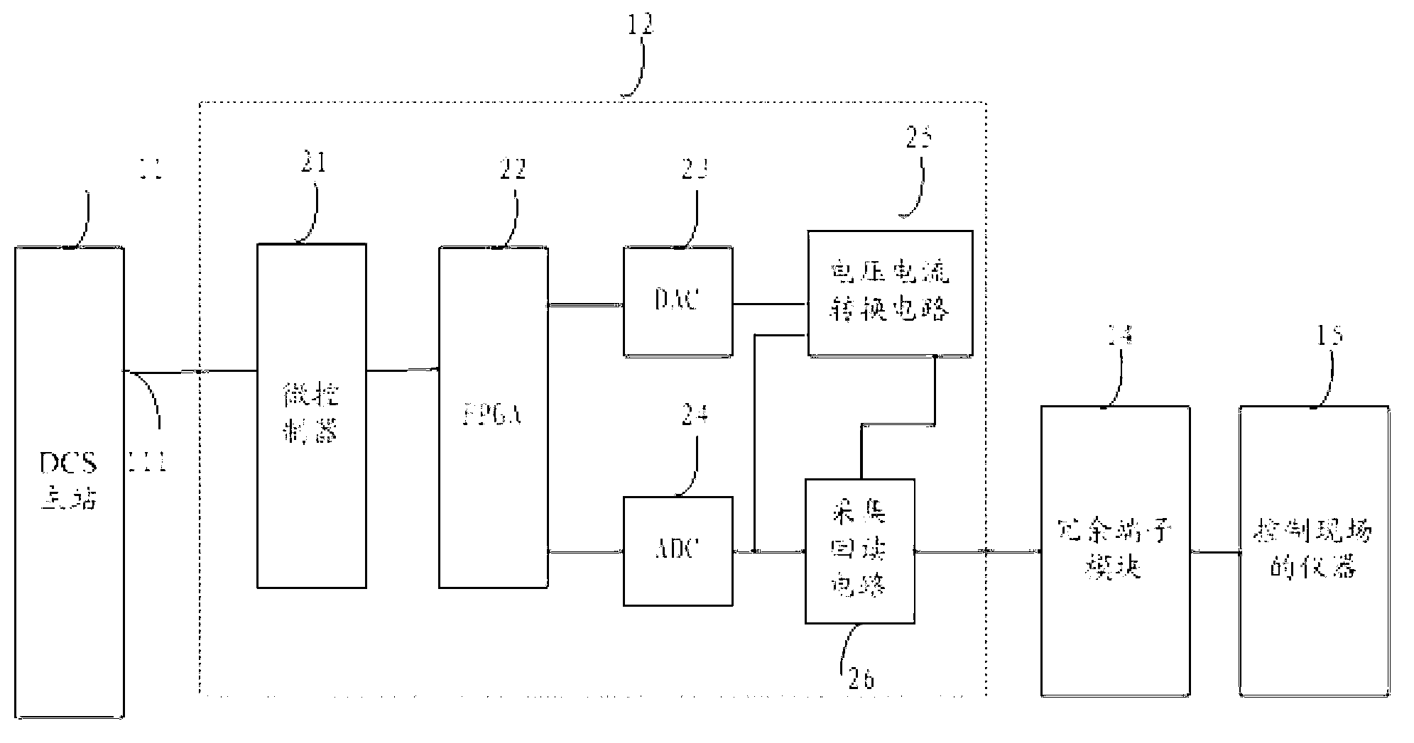
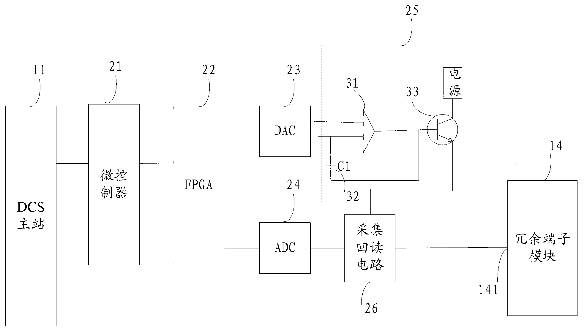
The invention discloses a redundant output device comprising a DCS (distributed control system) master station, a first output module, a second output module and a redundant terminal module. One end of the DCS master station is connected with one end of the first output module, while the other end of the DCS master station is connected with one end of the second output module. The other end of the first output module is connected with a first end of the redundant terminal module, while the other end of the second output module is connected with a second end of the redundant terminal. A third end of the redundant terminal is connected with an instrument for controlling a scene. The first output module and the second output module same in structure are connected through a redundant channel for mutual information. By the arrangement, current stroke upon the instrument for controlling the scene is reduced during the course when a certain output module which is out of order is replaced by another output module, so that service life of the instrument for controlling the scene can be prolonged.

Description

technical field [0001] The invention relates to the field of signal output, in particular to a redundant output device. Background technique [0002] In the distributed control system DCS (Distributed Control System), there will be a large number of instruments, transmitters, sensors and other instruments in the control field. In order to make the instruments on the control site work normally, the DCS master station needs to provide 4-20mA analog current signals (this analog current signal is a DC signal) to the instruments on the control site through the output device. [0003] In the prior art, in order to provide reliable current signals to instruments controlling the field, generally at least two output devices need to be equipped to realize redundant functions. Among the above multiple output devices, only one is the main output device, and the others are standby output devices. Under normal circumstances, only the main output device outputs current signals to the ins...

Claims


Application Information

Patent Timeline
Patent Type & Authority Applications(China)
IPC IPC(8): G05B19/418
CPCY02P90/02
Inventor 尹俊杰秦悦明杜辉行增晖肖素伟
Owner HANGZHOU HOLLYSYS AUTOMATION
Learn More