
Portable television antenna

A TV antenna, a portable technology, applied in the field of electronics, can solve the problems of complex TV antenna assembly process, inability to meet multi-directional requirements, easy to fall off the antenna, etc., and achieve the effect of being beneficial to viewing, excellent fixing performance, and reasonable structure

Inactive Publication Date: 2013-09-18
林伟良
View PDF0 Cites 0 Cited by
  • Summary
  • Abstract
  • Description
  • Claims
  • Application Information

AI Technical Summary

Problems solved by technology

[0002] The second industrial revolution brought human civilization into the electrical age, and electronic equipment has also become household names. After more than half a century of development, a series of products in the electronic field have become increasingly abundant, enriching our production and life, and antennas are an indispensable part of it. It is an indispensable and important part, and the application range of TV antenna is the most extensive. The antenna on the market is generally assembled from a support rod and an antenna. The structure is complex and the assembly is troublesome. It can no longer meet the multi-faceted needs of modern society. 7 discloses a portable TV antenna, including an outer cover, a parabolic revolving assembly, and a base. The base is provided with mounting screw holes. Corresponding to the fixing hole, the above-mentioned parabolic revolving assembly is fixed on the above-mentioned base through the threaded connector of the above-mentioned mounting screw hole and the fixing hole. The present invention solves the problem of the rotation of the parabolic revolving assembly of the mobile TV antenna during transportation. Reliable performance and simple implementation, but the assembly process of the TV antenna is complicated and the antenna is easy to fall off

Method used


Image

  • Portable television antenna

Examples


Embodiment Construction

[0011] In order to make the technical means, creative features, goals and effects achieved by the present invention easy to understand, the present invention will be further described below in conjunction with specific embodiments.

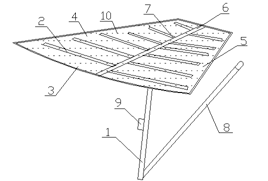
[0012] Such as figure 1 As shown, a portable TV antenna includes a support rod 1 and an antenna 2, the support rod 1 is provided with an antenna board 3, and the antenna board 3 includes a left board 4 and a right board 5, and the left board 4 and the right board 5 The right plate 5 is connected by a connecting rod 6, and the connecting rod 6 is provided with a plurality of slots 7, and the antenna 2 is fixed on the connecting rod 6 through the slot 7, which solves the problem of complicated installation of the TV antenna. The board is easy to disassemble and install, and the antenna can be used after aligning with the slot and inserting, and the antenna has excellent fixing performance and will not fall off. The structure is reasonable, practical...


PUM


Abstract

The invention discloses a portable television antenna which comprises a supporting rod and antenna bodies. An antenna plate is arranged on the supporting rod and comprises a left plate and a right plate which are connected through a connecting rod, a plurality of inserting grooves are formed in the connecting rod, and the antenna bodies are fixed on the connecting rod through the inserting grooves. By the portable television antenna, the problem of complexity in mounting of television antennas is solved; the left plate and the right plate are convenient to mount and demount, and the portable television antenna can be used once the antenna bodies are properly inserted into the inserting grooves; the portable television antenna is excellent in fixing performance, free of shedding, reasonable in structure, practical, convenient and suitable for popularization and use.

Description

technical field [0001] The invention relates to the field of electronics, in particular to a portable television antenna. Background technique [0002] The second industrial revolution brought human civilization into the electrical age, and electronic equipment has also become household names. After more than half a century of development, a series of products in the electronic field have become increasingly abundant, enriching our production and life, and antennas are an indispensable part of it. It is an indispensable and important part, and the application range of TV antenna is the most extensive. The antenna on the market is generally assembled from a support rod and an antenna. The structure is complex and the assembly is troublesome. It can no longer meet the multi-faceted needs of modern society. 7 discloses a portable TV antenna, including an outer cover, a parabolic revolving assembly, and a base. The base is provided with mounting screw holes. Corresponding to th...

Claims


Application Information

Patent Timeline
Patent Type & Authority Applications(China)
IPC IPC(8): H01Q1/12H01Q1/36H01Q1/40
Inventor 林伟良
Owner 林伟良
Learn More