A hydraulically activated reverse buckle and throw away mechanism

A technology of hands-off mechanism and hydraulic start, which is applied in wellbore/well components, earthwork drilling and production, etc. It can solve the problems of losing hands in advance and unable to rotate the pipe string in advance, and achieves the effect of wide application range

Inactive Publication Date: 2016-05-04
CHINA NAT PETROLEUM CORP CHUANQING DRILLING ENG CO LTD
View PDF8 Cites 0 Cited by
  • Summary
  • Abstract
  • Description
  • Claims
  • Application Information

AI Technical Summary

Problems solved by technology

[0006] The purpose of the present invention is to overcome the defect that the conventional left-handed thread undercutting and throwing mechanism cannot rotate the pipe string forward when the tool enters the well and before the operation is completed, and overcome the accidental shearing of the shear nails in the existing mechanical and hydraulic double-action throwing tools In order to solve the problem of losing hands in advance, a hydraulically activated back-off mechanism is provided. During the process of entering the well and before the completion of the operation, the pipe string can be rotated forward on the ground. The set shear nails are cut by the set pressure. The running resistance is borne by the left-handed thread, the shear pin is not stressed, and the tool will not be lost in advance; under abnormal circumstances, if the cycle pressure is high, the shear pin will be cut in advance, and the tool is still connected by the left-handed thread, and the tool will not be lost in advance , the function is more reliable and the security is higher

Method used


Image

  • A hydraulically activated reverse buckle and throw away mechanism

Examples


Embodiment 1

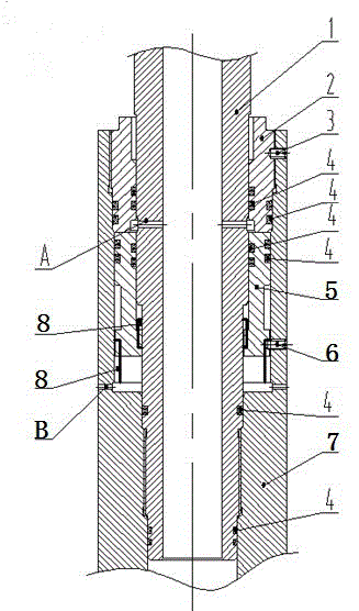
[0023] A hydraulically actuated back-and-forget mechanism, including a feed-in sub, a seal sleeve, a piston, and a drop-in sub, the feed-in sub 1 is connected to the drop-off sub 7 , and the drop-in sub 7 is connected to the feed-in sub 1 An annular space is formed between them, and the sealing sleeve 2 is arranged between the throwing short joint 7 and the feeding short joint 1 to seal the annular space to form an annular cavity. Keyed connection, the feeding nipple 1 is splined with the piston 5, and the piston 5 is positioned by the shear nail 6 and fixed on the hand nipple 7, the feeding nipple 1 has a first through hole A, the first through hole A respectively communicates with the inner hole of the feeding nipple 1 and the annular cavity on the upper part of the piston. There is a second through hole B on the throwing nipple 7, and the second through hole B is respectively connected to the annular cavity and the casing at the lower part of the piston 5. Annulus connectiv...

Embodiment 2

[0029] The present embodiment describes the present invention in detail:

[0030] A hydraulically actuated undercut mechanism, including a feed sub 1, a sealing sleeve 2, a set screw 3, an "O"-shaped sealing ring 4, a piston 5, a shear nail 6, and a drop sub 7, etc. The feeding sub-joint 1 is connected with the drop-off sub-joint 7 by a left-handed thread, and the first through hole A is opened on the feeding sub-joint 1 . A piston 5 is installed in the annulus between the feeding sub-joint 1 and the disengaging sub-joint 7, and the sealing sleeve 2 is connected with the disengaging sub-joint 7 through threads. The outer circle of the piston 5 is connected with the inner hole of the throwing short joint 7 by a spline 8, and the outer circle of the feeding joint 1 is connected with the inner hole of the piston 5 by a spline. The piston 5 is positioned by the shear pin 6 and fixed on the short joint 7. Under the action of the pressure difference between the upper and lower ends...


PUM


Abstract

The invention discloses a hydraulically started back-off releasing mechanism. A feeding sub is connected with a releasing sub; an annulus is formed between the releasing sub and the feeding sub; a sealing sleeve is arranged between the releasing sub and the feeding sub; a piston is arranged in the annulus cavity and is in splined joint with the releasing sub; the feeding sub is in splined joint with the piston; the piston is positioned by a shear pin and is fixedly arranged on the releasing sub; a first through hole communicated with an inner hole of the feeding sub and the annulus cavity of the upper part of the piston respectively is formed in the feeding sub; a second through hole communicated with the annulus cavity of the lower part of the piston and the annulus of a sleeve respectively is formed in the releasing sub. According to the hydraulically started back-off releasing mechanism, the defect that a pipe string cannot be rotated forwardly in the ground during tool descending and before completion of operation existing in the conventional left-hand thread back-off releasing mechanism can be overcome, and the problems of accidental shearing of the shear pin and advanced releasing of the tool existing in the conventional mechanical and hydraulic double-action releasing tool are also solved; the hydraulically started back-off releasing mechanism has higher reliability and a wider application range.

Description

technical field [0001] The invention relates to a hand-losing mechanism, in particular to a hydraulically activated back-and-forth hand-losing mechanism, which belongs to downhole tools. Background technique [0002] During drilling and downhole operations, some operating tools are sent to the working position through the feeding pipe string, and remain in the well after the operation is completed, and the feeding pipe string is lifted out of the ground through the release mechanism and the downhole tool. [0003] At present, the left-hand thread undercut mechanism is commonly used to realize tool throwing away. This mechanism is easy to operate and has been widely used in engineering practice. For example, what Chinese patent "CN201120415989.4" discloses is a kind of downhole pipe string dual-action hands-off device used in the petroleum industry. The disclosure date is July 11, 2012. There is a pressure relief hole, and the inner cavity is equipped with a ball seat, and t...

Claims


Application Information

Patent Timeline
Patent Type & Authority Patents(China)
IPC IPC(8): E21B23/08
Inventor 胡东锋叶文勇魏小房
Owner CHINA NAT PETROLEUM CORP CHUANQING DRILLING ENG CO LTD
Why Eureka
Try Eureka