BTB (board to board) rotary fastening device

A rotary buckle, board-to-board technology, applied in the direction of thin-plate connection, connecting components, mechanical equipment, etc., can solve the problems of loosening, detachment, sliding, tilting or detachment, etc., and achieve the effect of reliable assembly, simple operation and accurate positioning

Inactive Publication Date: 2013-09-25
HANWIT PRECISION IND LTD
View PDF6 Cites 6 Cited by
  • Summary
  • Abstract
  • Description
  • Claims
  • Application Information

AI Technical Summary

Problems solved by technology

[0003] Furthermore, see Figure 11 , Figure 12 , the currently used server case A includes a front cover A1, a rear cover A2 and a middle partition A3, wherein the front cover A1 and the rear cover A2 respectively cover the front of the server case A and the top of the rear chamber, and make the rear The front flange A21 of the cover A2 straddles the upper part of the upper flap A31 of the middle partition A3, and the stop grooves A22 are respectively positioned on the positioning protrusions A32, and then are locked by the middle engaging structure A11 of the front cover A1. Fit into the engagement groove A33 of the middle partition A3, and make the side of the front cover A3 combined with the front L-shaped groove with the front positioning protrusion, so that the front cover A1 and the rear cover A2 of the server chassis A can be matched The middle partition A3 forms a sliding fitting and locking state, but the front cover A1 and the rear cover A2 all use the fitting and locking method without a stable positioning function, and are easy to be moved or pulled out by the staff. When pulling on the server chassis A, the front cover A1 or the rear cover A2 will slide, tilt or fall off, and the front cover A1, the rear cover A2 and the middle partition A3 are only locked in one direction, which is also easy to cause The front cover A1 and the rear cover A2 are loosened and detached from the middle partition A3 due to the tilt during moving, and the overall structure is quite unstable, which needs to be redesigned by those engaged in this industry to effectively solve the problem

Method used


Image

  • BTB (board to board) rotary fastening device
  • BTB (board to board) rotary fastening device
  • BTB (board to board) rotary fastening device

Examples


Embodiment Construction

[0041] In order to achieve the above-mentioned purpose and effect, the technical means and the structure thereof adopted in the present invention are now illustrated in detail with respect to preferred embodiments of the present invention. Its features and functions are as follows, so that it can be fully understood.

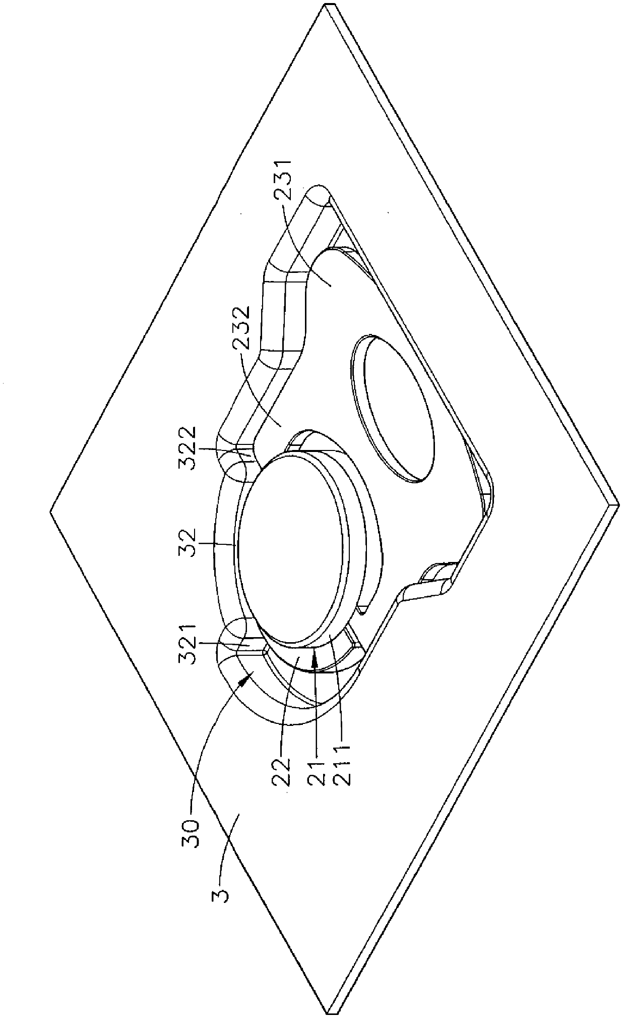
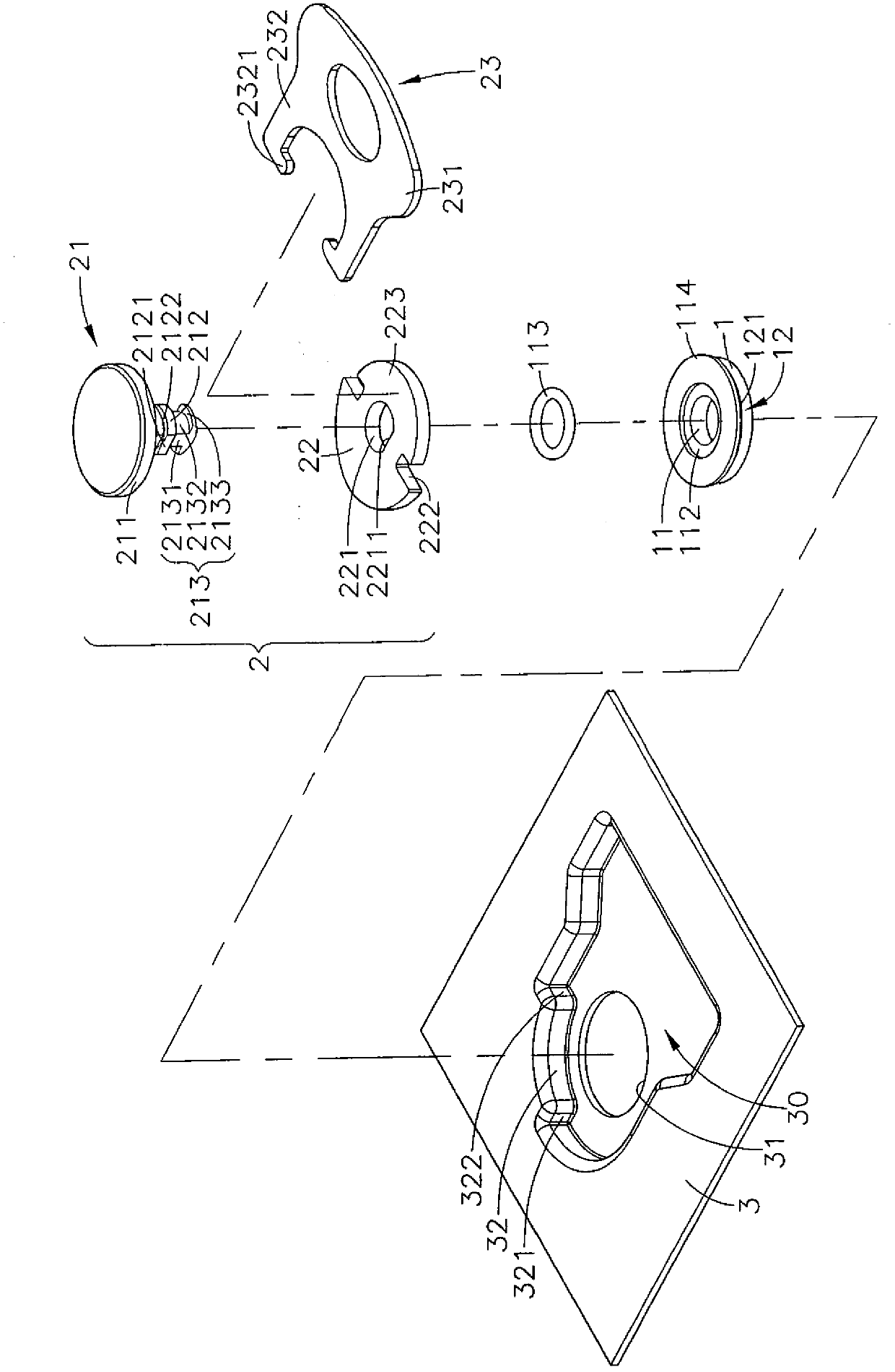
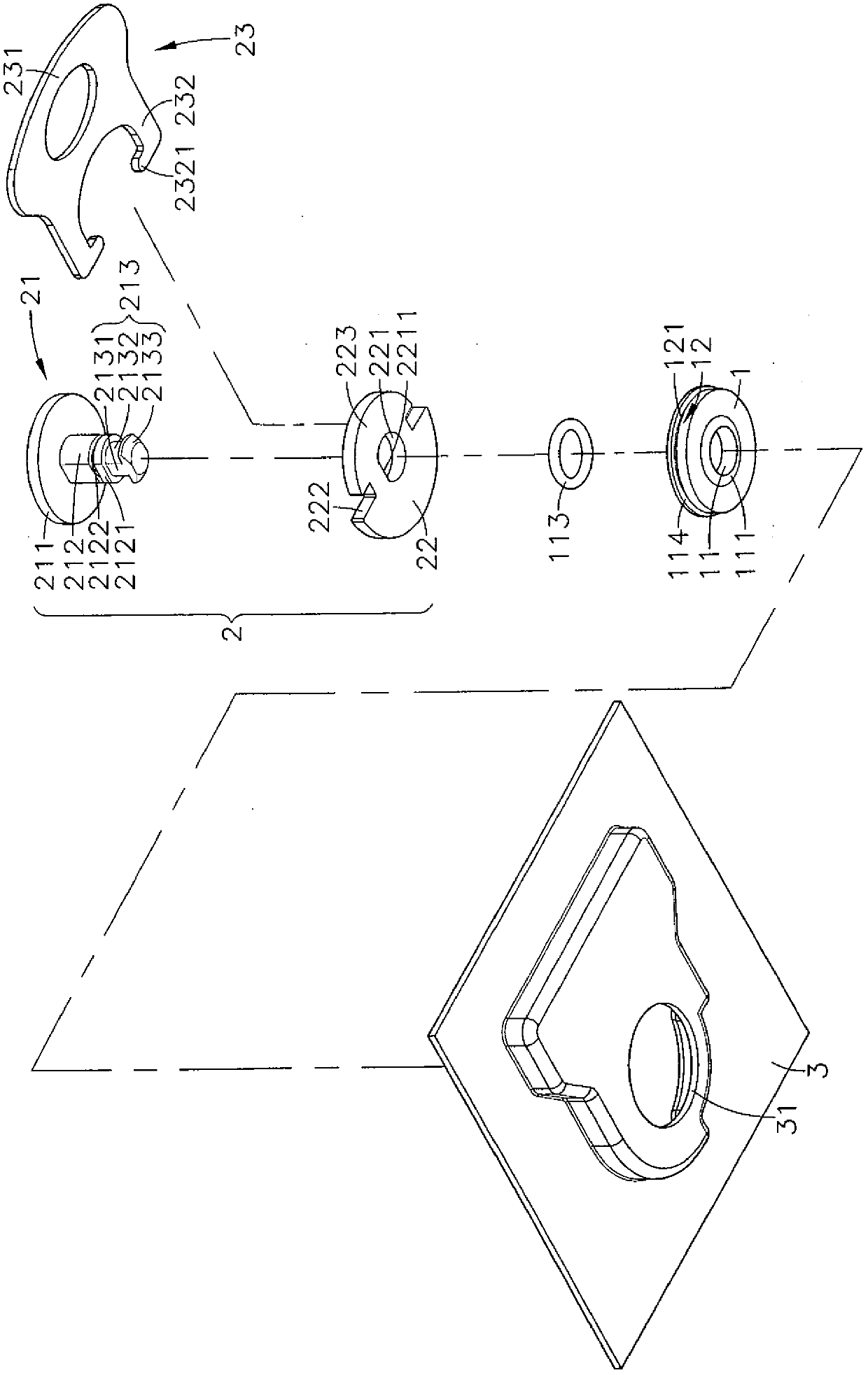
[0042] see figure 1 , figure 2 , image 3 , Figure 4 , are respectively the three-dimensional appearance diagram, the three-dimensional exploded view, the three-dimensional exploded view of another angle of view and the side sectional view of the present invention. It can be clearly seen from the figure that the present invention includes a docking sleeve 1 and a turnbuckle mechanism 2, wherein :

[0043] The hollow interior of the docking sleeve 1 has a perforation 11, and an annular stopper 111 is provided at the bottom periphery of the perforation 11, and the other side of the perforation 11 away from the annular stopper 111 is provided with a larger in...


PUM


Abstract

The invention relates to a BTB rotary fastening device which comprises a butt joint sleeve and a rotary fastening mechanism, wherein a penetration hole is formed in the butt joint sleeve, and a positioning part which is positioned in the position of a first pre-arranged plate body is arranged on the periphery of the outer side of the penetration hole; the rotary fastening mechanism comprises a buckling body and a swirling element positioned at a connecting part; the head part of the buckling body extends downward to form a rod body which penetrates through the penetration hole and extends downward as well as a fixing part; when a second pre-arranged plate body moves to the position of the first plate body, a longitudinal section relative to the fixing part can be aligned to the inner wall surface of a spacing groove of the second pre-arranged plate body, then the swirling element is pulled to rotate by 90 degrees, so that a stopping block which has no longitudinal section position on the fixing part of the buckling body is buckled in the spacing groove to form a locking state, further, the swirling element is reversely pulled to rotate to enable the fixing part to be separated from the spacing groove, the second pre-arranged plate body is quickly retreated, and accordingly, the effects of simple operation, firm assembly and accurate positioning are achieved.

Description

technical field [0001] The present invention provides a board-to-board rotating fastening device, especially refers to the fastening body that can be pulled in the docking sleeve to rotate 90 degrees to fasten the fixed part in the limiting groove of the second board body to form a locked state. It can also be reversely pulled on the buckle body so that the fixed part is separated from the limiting groove to quickly withdraw the second plate body and the first plate body, thereby achieving the effects of simple operation, reliable assembly and accurate positioning. Background technique [0002] With the continuous advancement of electronic technology, many products will use screws or pins for positioning, such as drawers, keyboard frames, board sets and other products with movable and telescopic structures, and use screws or pins to make slide rails and chute Positioning is formed when moving to a specific position, so that users can perform wiring operations, equipment move...

Claims


Application Information

Patent Timeline
Patent Type & Authority Applications(China)
IPC IPC(8): F16B5/00
Inventor 曾英智
Owner HANWIT PRECISION IND LTD
Why Eureka
Try Eureka