H half-bridge IPM bus voltage detection circuit

A bus voltage and detection circuit technology, applied in the direction of using digital measurement technology for measurement, can solve the problems of easy common mode interference, large signal delay, low reliability, etc., to solve the problem of resistance temperature drift, the circuit is simple, the solution The effect of common mode interference

Inactive Publication Date: 2013-09-25
GUANGDONG MINGYANG LONGYUAN POWER ELECTRONICS
View PDF5 Cites 2 Cited by
  • Summary
  • Abstract
  • Description
  • Claims
  • Application Information

AI Technical Summary

Problems solved by technology

For the first scheme using voltage Hall, its disadvantages are high price and large signal delay; for the second scheme using indirect measurement of voltage dividing resistors, its disadvantages are that it is susceptible to common-mode interference, large error when the temperature is high, and reliable Sex is not high

Method used


Image

  • H half-bridge IPM bus voltage detection circuit
  • H half-bridge IPM bus voltage detection circuit
  • H half-bridge IPM bus voltage detection circuit

Examples


Embodiment Construction

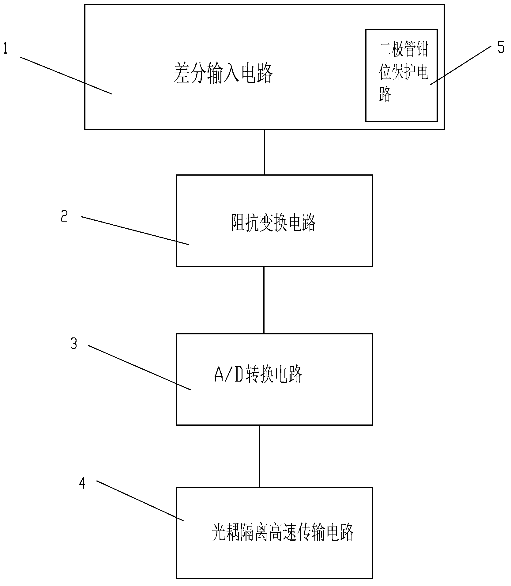
[0024] Such as figure 1 As shown, a H half-bridge IPM module bus voltage detection circuit includes:

[0025] Differential input circuit 1, its positive and negative input terminals +Vin, -Vin are connected to the positive and negative output terminals of the H half-bridge IPM module bus voltage;

[0026] Impedance transformation circuit 2, the input end of which is connected to the output end of differential input circuit 1;

[0027] A / D conversion circuit 3, the input end of which is connected to the output end of impedance transformation circuit 2, for analog-to-digital conversion of the input signal;

[0028] The optocoupler isolates the high-speed transmission circuit 4 , and its input terminal is connected with the output terminal of the A / D conversion circuit 3 .

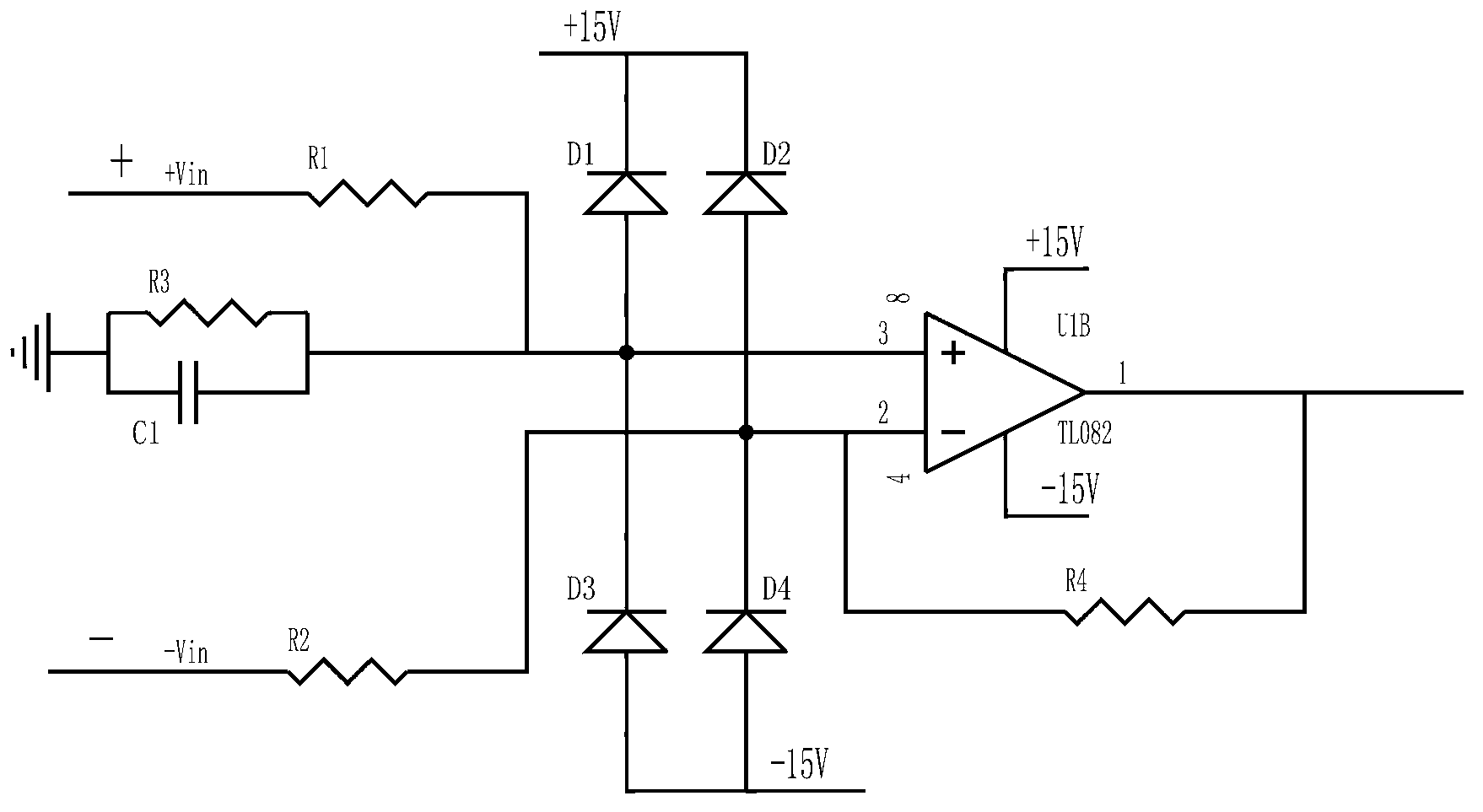
[0029] refer to figure 2 , the differential input circuit 1 of the present invention includes: a first differential amplifier U1B powered by an external DC ±15V; respectively arranged on the positive and ...


PUM


Abstract

The invention discloses an H half-bridge IPM bus voltage detection circuit which comprises a differential input circuit, an impedance transformation circuit, an A / D conversion circuit and an opto-coupler isolation high-speed transmission circuit. The input end of the differential input circuit is connected with the voltage positive output end and the voltage negative output end of an H half-bridge IPM bus. The input end of the impedance transformation circuit is connected with the output end of the differential input circuit. The input end of the A / D conversion circuit is connected with the output end of the impedance transformation circuit. The A / D conversion circuit is used for carrying out analog-digital conversion on input signals. The input end of the opto-coupler isolation high-speed transmission circuit is connected with the output end of the A / D conversion circuit. According to the H half-bridge IPM bus voltage detection circuit, the bus voltage is directly measured through the differential measuring mode, the problems of common-mode interference and resistance temperature excursions are solved, and the H half-bridge IPM bus voltage detection circuit is simple and low in cost. In addition, the H half-bridge IPM bus voltage detection circuit is provided with the opto-coupler isolation high-speed transmission circuit, and therefore electric isolation and long-distance transmission can be achieved.

Description

technical field [0001] The invention relates to a voltage detection circuit, in particular to a busbar voltage detection circuit of an H half-bridge IPM module of a fan converter. Background technique [0002] When the wind turbine converter is working, it is necessary to monitor the bus voltage of the power module (IPM) in real time in order to control the active and reactive power of the system. In the process of measuring the bus voltage of the power module (IPM), problems such as common mode interference, long-distance transmission, and electrical isolation need to be solved, so that the main control system can accurately and reliably detect the bus voltage of the power module (IPM). [0003] At present, the main methods of bus voltage measurement of the power module (IPM) are: 1. Direct measurement by voltage Hall; 2. Indirect measurement by voltage divider resistors, that is, use series resistors to divide the voltage and measure the voltage on the divider resistors. ...

Claims


Application Information

Patent Timeline
IPC IPC(8): G01R19/25
Inventor 付靖
Owner GUANGDONG MINGYANG LONGYUAN POWER ELECTRONICS
Why Eureka
Try Eureka