
Device for enlarging clear aperture of laser crystal and installing method thereof

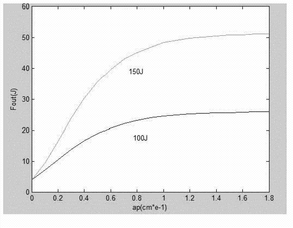
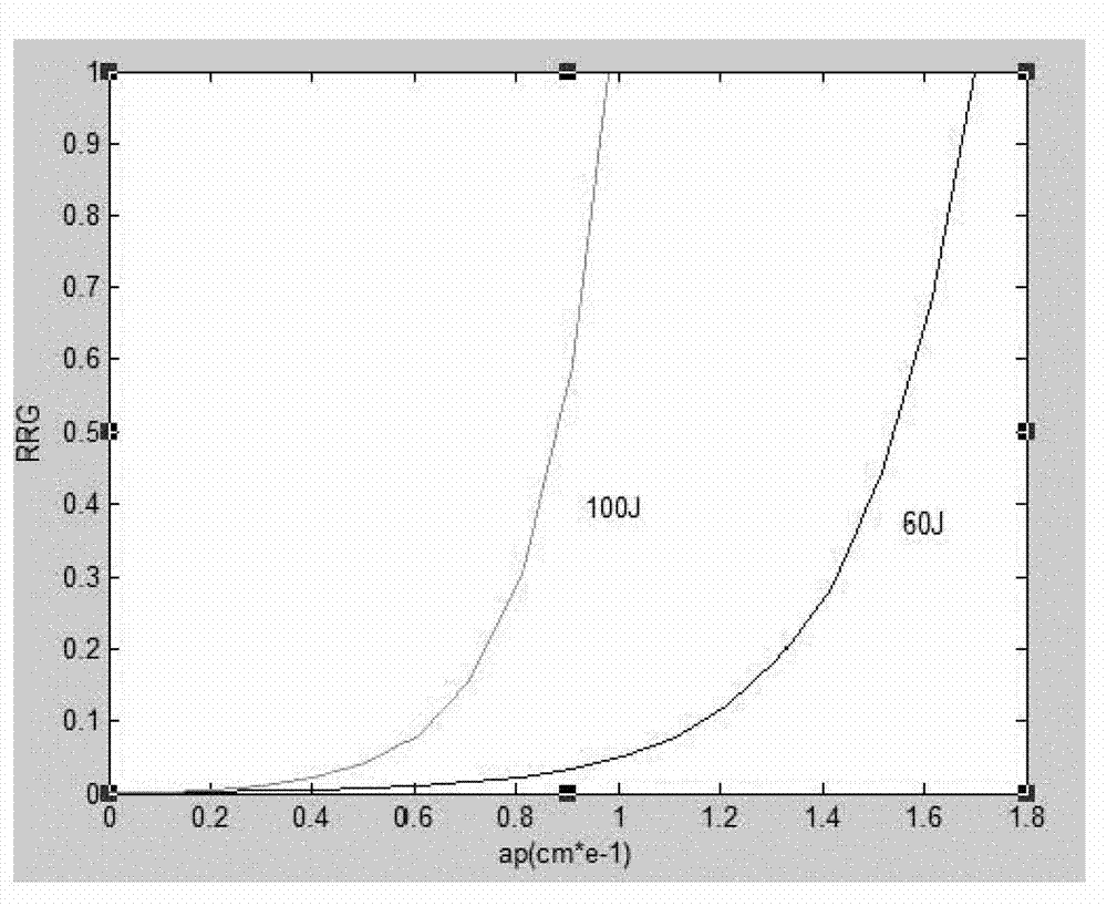
A technology of laser crystal and clear aperture, applied in laser parts, structure/shape of active medium, etc., can solve the problems of weak main pulse, influence modulation depth, different time-domain side lobe pulses, etc., to reduce energy density , The effect of simple adjustment and reduction of the influence of parasitic oscillation

Active Publication Date: 2013-09-25
SHANGHAI INST OF OPTICS & FINE MECHANICS CHINESE ACAD OF SCI
View PDF3 Cites 4 Cited by
  • Summary
  • Abstract
  • Description
  • Claims
  • Application Information

AI Technical Summary

Problems solved by technology

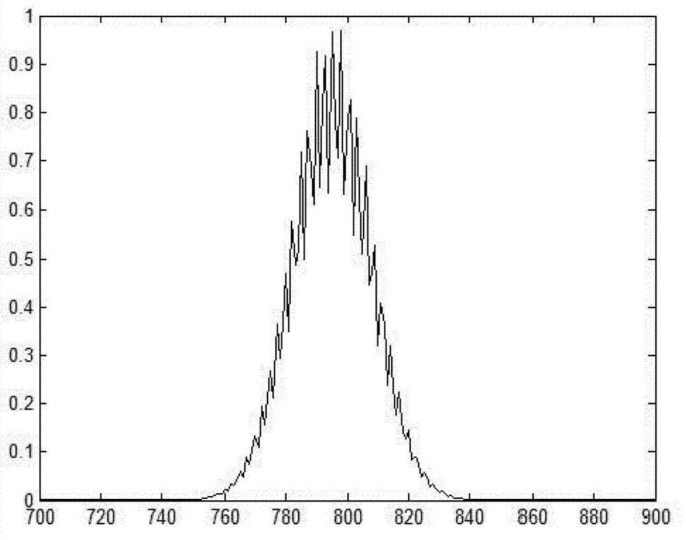
In addition, since laser crystals are mostly anisotropic, different optical axis orientations will produce different transmittances at different wavelengths and thus modulate the spectrum. See literature [Yuxin Leng, Lihuang Lin, Wenyao Wang, Yunhua Jiang, et al. , Optics&laser technology, 35, 425 (2003)] Through analysis such as image 3 and Figure 4 As shown: the modulation of the spectrum will cause the pulse to form two symmetrical sidelobe pulses in the time domain, and the different optical axis directions of the laser crystal will cause the time distance between the formed sidelobe pulse and the main pulse to be different. The length and the direction of the optical axis will also affect the modulation depth, making the size of the formed time-domain sidelobe pulse different, and the larger sidelobe will make the main pulse weaker

Method used


Image

  • Device for enlarging clear aperture of laser crystal and installing method thereof
  • Device for enlarging clear aperture of laser crystal and installing method thereof
  • Device for enlarging clear aperture of laser crystal and installing method thereof

Examples


Embodiment Construction

[0028] see Figure 7 , the present invention laser crystal optical aperture expansion device, this device comprises laser crystal 6, fixing frame 1 and bolt 2 and bolt 3, the positional relationship of above-mentioned components and parts is as follows:

[0029] The fixed frame 1 includes two identical clamps, the clamps are a cylindrical structure with an inner right angle and an outer circle, and two screw holes 4 and screw holes perpendicular to the joint surface of the two clamps are provided in the bodies of the two clamps. 5. Two bolts 2 and 3 pass through the screw holes 4 and 5 to form an outer cylinder with a square elongated hole inside. The square elongated hole is concentric with the outer cylinder. The spliced ​​laser crystal 6 is placed in the square inner hole of the fixing frame, and locked by the bolt 2 and the bolt 3 described above.

[0030] The splicing seams of the laser crystal 6 are filled with fillers 7, including absorber wrapping of colloidal materia...


PUM


Abstract

Provided are a device for enlarging a clear aperture of a laser crystal, and an installing method of the device for enlarging the clear aperture of the laser crystal. The device for enlarging the clear aperture of the laser crystal comprises the laser crystal, a fixing support, a first bolt and a second bolt. According to the position relation of the components, the fixing support comprises two identical fixtures, each fixture is of a cylinder structure, the inner side of each fixture is of a right-angle shape, the outer side of each fixture is round, a first screw hole and a second screw hole are formed inside the two fixtures, and are perpendicular to the combining faces of the two fixtures, the two bolts penetrate through the first screw hole and the second screw hole to form an outer cylinder, a long square hole is formed in the outer cylinder, the long square hole and the outer cylinder are concentric, and the spliced laser crystal is placed in the square inner hole of the fixing support, and is locked through the first bolt and the second bolt. The device for enlarging the clear aperture of the laser crystal and the installing method of the device for enlarging the clear aperture of the laser crystal effectively enlarge the clear aperture of the laser crystal, can reduce parasitic oscillation and the heat effect, and have the advantages of being easy to adjust, convenient to install, stable in structure and low in cost.

Description

technical field [0001] The invention relates to a laser amplifying device, in particular to a laser crystal light aperture expanding device based on splicing technology and an installation method thereof. Background technique [0002] In recent years, with the continuous in-depth development of strong field science and the continuous improvement of the energy and intensity requirements of ultra-intense and ultra-short lasers, various optical amplification devices have been greatly developed. In this system, laser crystals are the core devices. To obtain high-energy and high-intensity laser pulses often requires a laser crystal with a large optical aperture and a strong pump light. However, large-sized laser crystals and high-energy-density pump light will bring some problems at the same time, including the limitation of laser crystal growth technology, the inability to obtain large enough laser crystals; The laser parasitic oscillation between the sides of the crystal, the ...

Claims


Application Information

Patent Timeline
Patent Type & Authority Applications(China)
IPC IPC(8): H01S3/06H01S3/07H01S3/02
Inventor 刘彦祺冷雨欣印定军陆效明许毅陆海鹤梁晓燕李儒新徐至展
Owner SHANGHAI INST OF OPTICS & FINE MECHANICS CHINESE ACAD OF SCI
Learn More