
High-power contactless module switch

A high-power, non-contact technology, applied in the direction of reactive power adjustment/elimination/compensation, substation/switchgear cooling/ventilation, reactive power compensation, etc., can solve the waste of electric energy, high system cost and unsafe use and other issues, to achieve the effect of convenient installation and use, low cost, and huge economic and social benefits

Active Publication Date: 2015-07-08
XINXIANG STRONG POWER ELECTRIC
View PDF4 Cites 0 Cited by
  • Summary
  • Abstract
  • Description
  • Claims
  • Application Information

AI Technical Summary

Problems solved by technology

[0003] In view of the above situation, the purpose of the present invention is to provide a high-power non-contact modular switch, which can be safely used in harsh environments and unbalanced on-site loads, and can solve the problems of waste of electric energy, high system cost, and unsafe use. question

Method used


Image

  • High-power contactless module switch
  • High-power contactless module switch
  • High-power contactless module switch

Examples


Embodiment Construction

[0012] The specific embodiments of the present invention will be described in detail below with reference to the accompanying drawings.

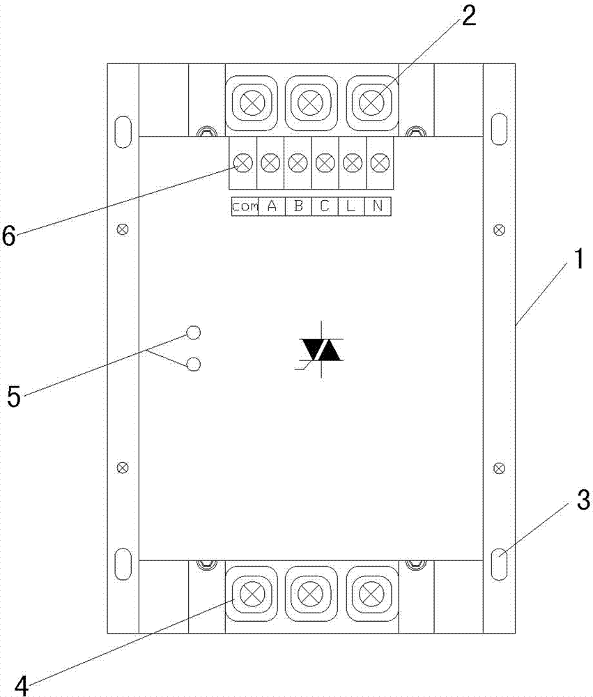
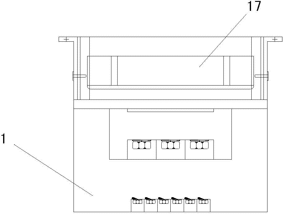
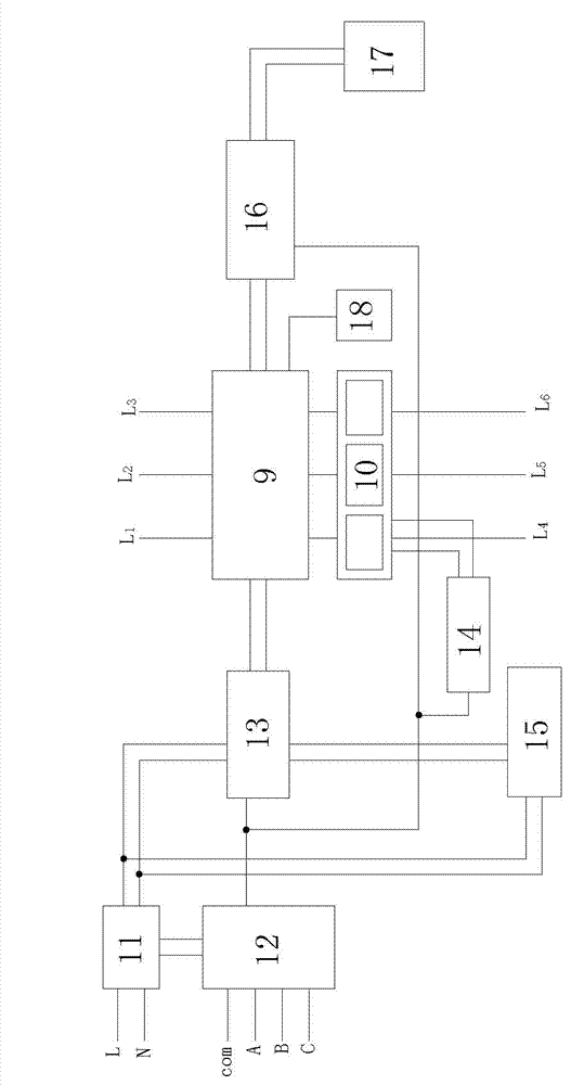
[0013] by Figure 1-4 As shown, the present invention includes a box body and a control circuit in the box body. The upper part of the circuit board 1 in the box body 1a has 3 incoming terminals 2 and the lower part of the circuit board has 3 outgoing terminals 4. The current and working status indicator lights 5 connected to the controller, 3 incoming terminals 2 The lower circuit board is provided with the controller's common line com terminal, three-phase wire A, B, C terminal and two rectifiers The terminal 6 is composed of L and N wire terminals. The control circuit includes a controller 12, a trigger 13, a zero-crossing detector 15 and a high-power thyristor switch (or TSC high-power non-contact switch) 9 , The common line com, three-phase lines A, B, and C of the controller 12 are respectively connected to the common line com terminal an...


PUM


Abstract

The invention relates to a high-power contactless module switch, which solves the problems of electric energy waste, high system cost and unsafe use. The high-power contactless module switch is structurally characterized in that a wire incoming terminal, a wire outgoing terminal, and a current and working state indication lamp connected with a controller are arranged on a circuit board in a box body; a wire connecting terminal is arranged on the circuit board below the wire incoming terminal; a control circuit comprises the controller, a trigger, a zero-passage detector and a high-power silicon-controlled switch; the controller is connected with the wire connecting terminal and an external control room and is also connected with a rectifier, the trigger, a protector and a temperature control switch respectively; the rectifier is connected with the wire connecting terminal; the trigger is connected with the rectifier and the zero-passage detector via a common terminal; the trigger is connected with the zero-passage detector and the high-power silicon-controlled switch respectively; the high-power silicon-controlled switch is connected with a fan via the temperature control switch; an electric energy recoverer is connected with the high-power silicon-controlled switch. The high-power contactless module switch disclosed by the invention is convenient and safe to install and use, low in cost and easy to produce, and has the effects of energy conservation and environment protection.

Description

technical field [0001] The invention relates to electrical appliances, in particular to a high-power non-contact module switch. Background technique [0002] High-power non-contact switches are commonly used equipment in power transmission. At present, regarding power quality, enterprise standards are low, and there are many nonlinear loads. The large harmonic currents cause three-phase imbalances that seriously exceed national standards. The non-contact switches sold in the market all have a capacity of less than 60Kvar and low protection performance, especially in harsh environments, unbalanced on-site loads, and high system costs. Since the thyristor is a heating device, the power waste is serious. Therefore, the existing non-contact The use of the switch is not satisfactory, and its innovation and improvement are imperative. Contents of the invention [0003] In view of the above situation, the purpose of the present invention is to provide a high-power non-contact mo...

Claims


Application Information

Patent Timeline
Patent Type & Authority Patents(China)
IPC IPC(8): H02J3/18H02B1/56
CPCY02E40/30
Inventor 张新红
Owner XINXIANG STRONG POWER ELECTRIC
Learn More