Discharge circuit, communication device and discharge method

A discharge circuit and equipment technology, applied in the field of communication, can solve problems such as small discharge circuit, chip damage, and accelerated discharge speed

Active Publication Date: 2017-03-08
MAIPU COMM TECH CO LTD
View PDF4 Cites 2 Cited by
  • Summary
  • Abstract
  • Description
  • Claims
  • Application Information

AI Technical Summary

Problems solved by technology

[0002] At present, most communication devices such as routers and switches contain a large number of energy storage capacitors, so when the device is powered off, it takes a long time to complete the discharge. The chip is damaged due to the completion of the operation
[0003] In order to speed up the discharge speed of communication equipment, most communication equipment manufacturers adopt the method of adding "dummy load" to the power supply to provide a path to the ground for the equipment. The "dummy load" here is generally a large resistance to prevent The current on this discharge circuit is very small, so the effect of accelerating the discharge speed is not obvious

Method used


Image

  • Discharge circuit, communication device and discharge method
  • Discharge circuit, communication device and discharge method
  • Discharge circuit, communication device and discharge method

Examples


Embodiment 1

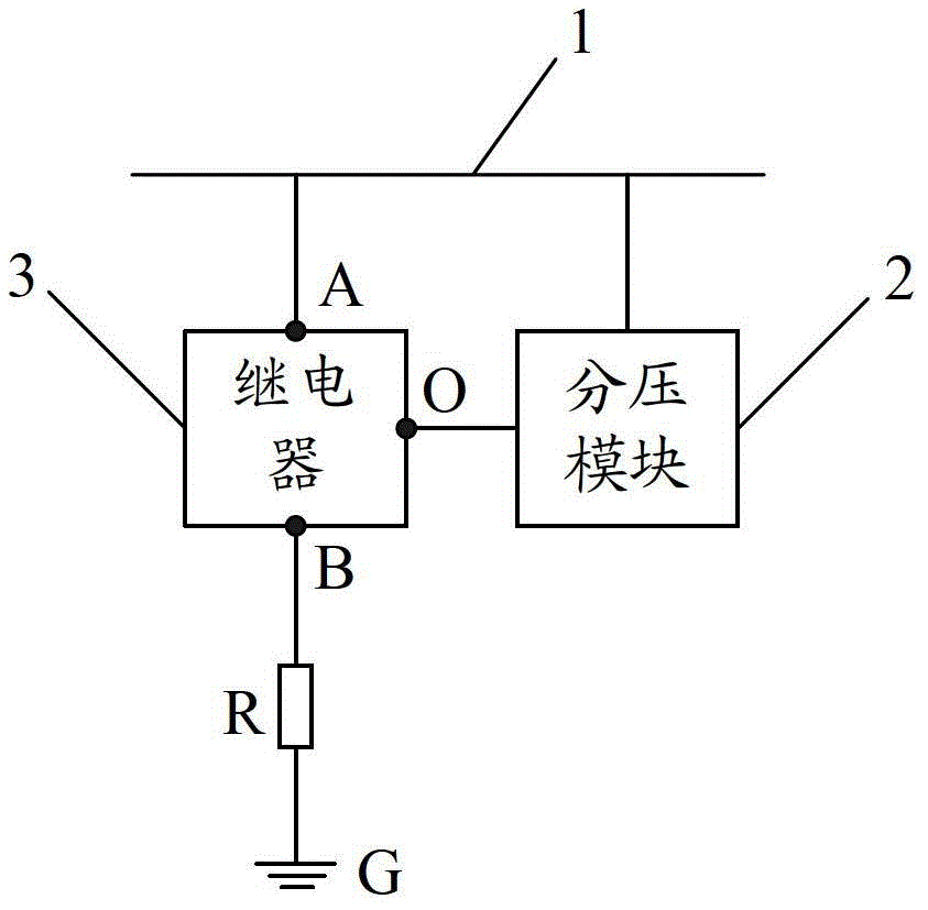
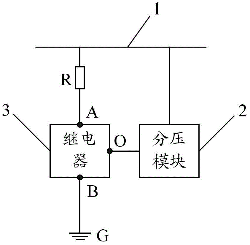
[0043] like figure 1 As shown, the embodiment of the present invention provides a discharge circuit, including: a power supply line 1; a voltage divider module 2, the input end of which is connected to the power supply line 1; a relay 3, the relay 3 includes a control terminal O and a normally closed contact group, and the control The terminal O is connected to the output terminal of the voltage divider module 2, the first contact A in the normally closed contact group is connected to the power supply line 1, and the second contact B in the normally closed contact group is connected to the ground terminal G; the power resistor R, such as figure 2 As shown, the power resistor R is connected in series between the first contact A and the power supply line 1, or as figure 1 As shown, the power resistor R is connected in series between the second contact B and the ground terminal G. Specifically, the voltage dividing module 2 may be a resistor.

[0044] The discharge circuit ca...

Embodiment 2

[0047] On the basis of the first embodiment, further, the above-mentioned relay may only include a normally closed contact group, however, commonly used relays are usually single-pole double-throw. SPDT relays include common contacts, normally closed contacts and normally open contacts, the common contacts and normally closed contacts form the above normally closed contact group, and the common contacts and normally open contacts form the normally open contact group , when the control terminal voltage of the relay is below the preset value, the public contact and the normally closed contact are closed, and the public contact is disconnected from the normally open contact. When the control terminal voltage of the relay is above the preset value, the public contact The point is disconnected from the normally closed contact, and the common contact is closed from the normally open contact; in this embodiment, the normally open contact is suspended; if figure 1 As shown, the common...

Embodiment 3

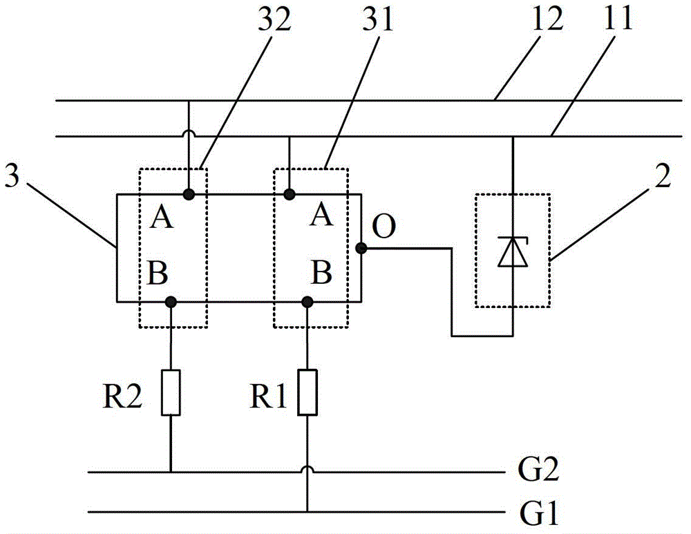
[0051] On the basis of embodiment one or embodiment two, further, as image 3 As shown, the power supply line can include a main power supply line 11 and an auxiliary power supply line 12; the input end of the voltage divider module 2 is connected to the main power supply line 11, and the output end of the voltage divider module 2 is connected to the control terminal O of the relay 3; the normally closed contact The point group includes the main normally closed contact group 31 and the auxiliary normally closed contact group 32; the ground terminal includes the main ground terminal G1 and the auxiliary ground terminal G2; the power resistance includes the main power resistance R1 and the auxiliary power resistance R2; the main normally closed contact The first contact A in the point group 31 is connected to the main power supply line 11, the second contact B in the main normally closed contact group 31 is connected to the main ground terminal G1, and the main power resistor is ...


PUM


Abstract

The invention discloses a discharging circuit, communication equipment and a discharging method and relates to the technical field of communication, so that the discharging speed can be effectively increased, and therefore, the damage of a chip caused by misoperation in the event that discharging is not completed in testing and inspecting processes is avoided. The discharging circuit comprises a power supply circuit, a voltage-dividing module, a relay and a power resistor, wherein the input end of the voltage-dividing module is connected to the power supply circuit; the relay comprises a control end and a normally closed contact set; the control end is connected to the output end of the voltage-dividing module; the first contact in the normally closed contact set is connected to the power supply circuit; the second contact in the normally closed contact set is connected to the grounded end; the power resistor is connected between the first contact and the power supply circuit in series; or, the power resistor is connected between the second contact and the grounded end in series.

Description

technical field [0001] The invention relates to the technical field of communication, in particular to a discharge circuit, communication equipment and a discharge method. Background technique [0002] At present, most communication devices such as routers and switches contain a large number of energy storage capacitors, so when the device is powered off, it takes a long time to complete the discharge. Completing the operation results in damage to the chip. [0003] In order to speed up the discharge speed of communication equipment, most communication equipment manufacturers adopt the method of adding "dummy load" to the power supply to provide a path to the ground for the equipment. The "dummy load" here is generally a large resistance to prevent The current on the discharge circuit is very small, so the effect of accelerating the discharge speed is not obvious. Contents of the invention [0004] The invention provides a discharge circuit, a communication device and a ...

Claims


Application Information

Patent Timeline
Patent Type & Authority Patents(China)
IPC IPC(8): H04L12/26
Inventor 刘勇军章波
Owner MAIPU COMM TECH CO LTD
Why Eureka
Try Eureka