
Method and device for controlling the temperature of steam in a boiler

A steam temperature and boiler technology, applied in boiler cleaning control devices, control systems, steam generation, etc., can solve problems affecting the adjustment process, troublesome and complicated boiler thermal adjustability, and achieve cost-saving effects

Active Publication Date: 2013-09-25
SIEMENS ENERGY GLOBAL GMBH CO & KG
View PDF6 Cites 4 Cited by
  • Summary
  • Abstract
  • Description
  • Claims
  • Application Information

AI Technical Summary

Problems solved by technology

[0015] In summary, it can be concluded that the thermal adjustability of boilers mainly based on combustion and point injection cooling, aiming at the stable and optimal thermal state of the boiler, is very cumbersome and complex
Especially with the disadvantage that thermal imbalances always occur
Additional problems arise due to fouling in the boiler area, which always affects the heat transfer over the heat exchanger tubes and negatively affects the conditioning process

Method used


Image

  • Method and device for controlling the temperature of steam in a boiler
  • Method and device for controlling the temperature of steam in a boiler
  • Method and device for controlling the temperature of steam in a boiler

Examples


Embodiment Construction

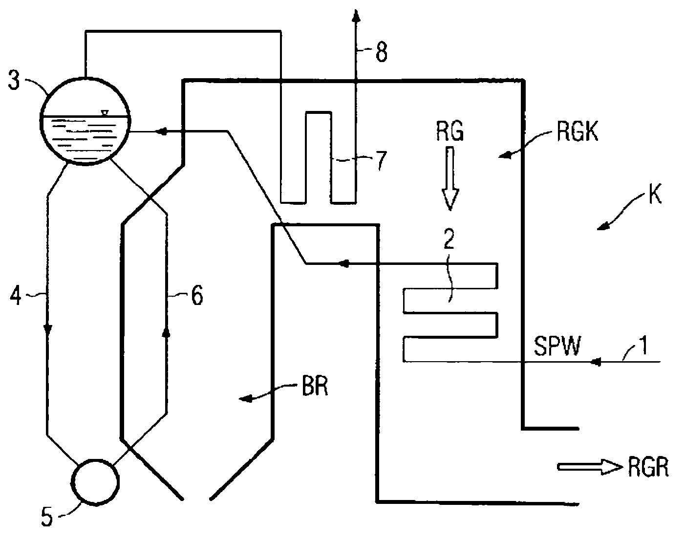
[0042] figure 1 The steam generator is shown in a very simplified form. In the combustion chamber BR of the boiler K, solid fossil fuels such as carbon dust are burned. The flue gas RG produced in this process is conducted via a flue gas line RGK to a flue gas cleaning device RGR. Evaporation of the supply water SPW takes place in the piping of the evaporation chamber and in the piping of the heat exchanger. The system is generally configured such that feedwater is supplied from a feedwater tank 1 to a feedwater preheater 2 (ECO). From the preheater, the water-steam mixture enters the drum 3 and is fed to the superheater (7 or ), which is then supplied to the turbine 8. Additionally, the superheater Can also include reheater

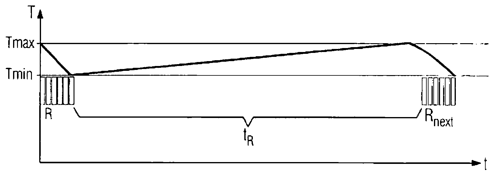
[0043] According to the invention on which this application is based, the steam temperature is controlled and regulated by means of a sootblower device which creates a certain fouling on the heat exchanger surfaces inside the boiler.

[0044] ...


PUM


Abstract

The invention relates to a method and a corresponding device for controlling the temperature of steam in a boiler of a steam generator, whereby the gradual accumulation of dirt on heat exchanger surfaces inside the boiler is incrementally regulated by means of soot blowers. The targeted influencing of the heat transfer on the heat exchanger surfaces enables the steam temperatures to be controlled and regulated.

Description

technical field [0001] The invention relates to a method for controlling the temperature of steam in a boiler and to a corresponding device. Background technique [0002] A fossil fuel steam generator or boiler for a power plant typically includes a combustion chamber, an evaporator chamber, and a heat exchanger system connected to the evaporator chamber. There are many different embodiments of boiler construction, such as drum boilers or Bunsen boilers. In a variant, the evaporator chamber comprises a duct arrangement in direct thermal contact with the combustion chamber. In the evaporator chamber, the feedwater output from the feedwater preheater is evaporated to saturated steam temperature. The steam is then directed through a heat exchanger system, also usually tubular, in which the temperature of the steam is adjusted to the inlet temperature required by the turbine. A heat exchanger system usually consists of at least one superheater, reheater, economizer and air pr...

Claims


Application Information

Patent Timeline
Patent Type & Authority Applications(China)
IPC IPC(8): F22B37/56
CPCF22B35/00F22B37/56F28G1/16Y10T137/0419F28G15/003F28G9/00
Inventor K.赫特韦克
Owner SIEMENS ENERGY GLOBAL GMBH CO & KG
Learn More