Automatic inflating flower-drum

An automatic inflation and hub technology, applied in tire measurement, wheel hubs, tire parts, etc., can solve problems such as inability to drive users, tire damage, inflation, etc.

Inactive Publication Date: 2013-10-02
WUXI MATEX PRECISION
View PDF0 Cites 0 Cited by
  • Summary
  • Abstract
  • Description
  • Claims
  • Application Information

AI Technical Summary

Problems solved by technology

[0002] At present, common vehicles such as electric vehicles on the market are usually unable to automatically inflate the tires during driving. Inconvenience

Method used


Image

  • Automatic inflating flower-drum
  • Automatic inflating flower-drum

Examples


Embodiment Construction

[0018] The present invention will be described in further detail below according to the drawings and embodiments.

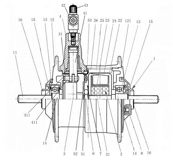
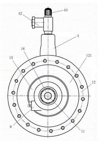
[0019] like figure 1 and figure 2 As shown, a self-inflating hub described in the embodiment of the present invention includes a hub assembly 1, and the hub assembly 1 includes a central shaft 11 and a hub shell 12, and a sleeve is set between the central shaft 11 and the hub shell 12. There is a motor assembly 2 for driving the hub shell 12 to rotate around the central shaft 11; a cam 3 is fixedly arranged on the central shaft 11; an air pump 4 is fixedly mounted on the outer wall of the hub shell 12, and the The piston rod 41 of the air pump 4 passes through the outer wall of the hub shell 12 and is connected to the cam 3 .

[0020] Specifically, the cam 3 has a rotary wheel 31, the rotary wheel 31 has a track groove 311, and the bottom of the piston rod 41 is provided with a sliding connection part 411 matched with the track groove 311, and the sliding conn...


PUM


Abstract

The invention relates to an automatic inflating flower-drum, comprising a flower-drum component, wherein the flower-drum component comprises a center shaft and a flower-drum housing; a motor component is sleeved between the center shaft and the flower-drum housing, and used for driving the flower-drum housing to rotate around the center shaft; a cam is fixedly arranged on the center shaft; an inflator pump is fixedly arranged at the outer wall of the flower-drum housing; a piston rod of the inflator pump passes through the outer wall of the flower-drum housing and is connected to the cam. The flower-drum housing is driven to rotate around the center shaft by the motor component, so as to drive the inflator pump to rotate around the cam. Thus, automatic inflating of tires in the wheel movement process is achieved.

Description

technical field [0001] The invention relates to a wheel hub, in particular to an automatic inflatable hub applied to an electric vehicle. Background technique [0002] At present, common vehicles such as electric vehicles on the market are usually unable to automatically inflate the tires during driving. Inconvenience. Contents of the invention [0003] The object of the present invention is to overcome the above-mentioned problems in the prior art, and provide an automatic inflation hub, which can automatically inflate the tires during the movement of the wheels. [0004] The purpose of the present invention is to realize through the following technical solutions: [0005] A self-inflating hub, including a hub assembly, the hub assembly includes a central shaft and a hub shell, and a motor assembly is set between the central shaft and the hub shell to drive the hub shell around the central shaft Rotation: a cam is fixedly arranged on the central shaft, an air pump is f...

Claims


Application Information

Patent Timeline
Patent Type & Authority Applications(China)
IPC IPC(8): B60C23/12B60B27/04
CPCB60C23/127B60C23/137
Inventor 的场年昭
Owner WUXI MATEX PRECISION
Why Eureka
Try Eureka