A cam plate position differential detection device

A differential detection, cam plate technology, applied in the direction of measuring device, transmission device, belt/chain/gear, etc., can solve the problems of machine disorder, huge machine, high equipment cost, etc., and achieve the effect of simplifying the structure and reducing equipment cost.

Active Publication Date: 2015-08-05
王研
View PDF5 Cites 0 Cited by
  • Summary
  • Abstract
  • Description
  • Claims
  • Application Information

AI Technical Summary

Problems solved by technology

[0002] In the production of metal packaging cans, in order to realize fully automated operations on the same machine, while sealing the cans, it is also necessary to perform actions such as rounding and capping at the same time. In order to achieve orderly sealing, rounding, and capping It must be driven by the gear system to achieve a consistent pace, so the gear system is very large, the entire machine is very large, and the equipment cost is high; and there is also a phenomenon that the entire machine is in a disordered state due to the accumulation of errors
In order to simplify the structure of the whole machine, someone thought of using the electric eye to detect the real-time position of the cam plate used to feed the seaming roller, and according to the real-time position of the cam plate, directly send electric signals to the actuators of the round edge and capping, so as to achieve various The actuators are in step, but because the cam plate and the actuator driven by the cam plate are rotating, there is no place to install the electric eye, and the problem cannot be finally solved

Method used


Image

  • A cam plate position differential detection device

Examples


Embodiment Construction

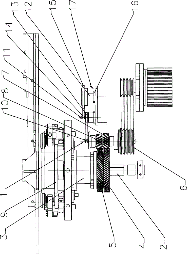
[0009] The present invention will be further described below in conjunction with the accompanying drawings and embodiments.

[0010] refer to figure 1 , the cam plate position differential detection device of this embodiment includes a drive shaft 1 mounted on the chassis and a fixed shaft 2 fixedly mounted on the chassis, and a belt that can rotate freely is set on the fixed shaft 2 through a bearing. There is a rotary body 3 with a working turntable, and an upper gear 4 is fixedly installed on the rotary body 3. A clutch gear 5 is also installed on the rotary body 3 through a copper sleeve. The clutch gear 5 and the rotary body 3 can produce relative rotation, and the upper gear 4 There is a differential with the clutch gear 5 in the rotation process. A large pulley 6, an upper helical gear 7 and a lower helical gear 8 are respectively fixedly installed on the transmission shaft 1, the upper helical gear 7 transmits the power from the large pulley 6 to the upper gear 4, and...


PUM


Abstract

The invention discloses a position difference detection device of a cam plate. The device is composed of an upper inclined gear arranged on a transmission shaft, a lower inclined gear arranged on the transmission shaft, an upper gear arranged on a fixing shaft, and a clutch gear. The transmission shaft is further provided with a synchronous wheel I, a machine box is provided with a gap bridge shaft and a detection shaft, a gap bridge shaft upper key is fixedly provided with a synchronous wheel II and a synchronous wheel III, a detection shaft upper key is fixedly provided with a synchronous wheel IV, the synchronous wheel I and the synchronous wheel II are connected through a transmission belt, and the synchronous wheel III and the synchronous wheel IV are connected through a transmission belt. The detection shaft is further provided with a simulated cam plate consistent with the cam plate. The tooth number of the upper inclined gear, the tooth number of the lower inclined gear, the tooth number of the synchronous wheel I and the tooth number of the synchronous wheel III are equal. The tooth number of the synchronous wheel II and the tooth number of the upper gear are equal. The tooth number of the synchronous wheel IV and the tooth number of the synchronous wheel III form a mathematic relation. The position difference detection device achieves measurement of real-time position information of the cam plate by means of electric eyes. Therefore, the structure of a machine is simplified, and equipment cost is reduced.

Description

technical field [0001] The invention relates to a metal packaging industry, especially a tinplate packaging machine, in particular to a cam plate position differential detection device. Background technique [0002] In the production of metal packaging cans, in order to realize fully automated operations on the same machine, while sealing the cans, it is also necessary to perform actions such as rounding and capping at the same time. In order to achieve orderly sealing, rounding, and capping The progress must be driven by the gear system to achieve a consistent pace, so the gear system is very large, the entire machine is very large, and the equipment cost is high; and there is also a phenomenon that the entire machine is in a disordered state due to the accumulation of errors. In order to simplify the structure of the whole machine, someone thought of using the electric eye to detect the real-time position of the cam plate used to feed the seaming roller, and according to t...

Claims


Application Information

Patent Timeline
Patent Type & Authority Patents(China)
IPC IPC(8): F16H37/12G01B21/00B21D51/26
Inventor 姚岱玲
Owner 王研
Why Eureka
Try Eureka