Super-plastic forming die and method thereof

A superplastic molding and mold technology, applied in the field of manufacturing, can solve the problems of inconsistent thickness uniformity of workpieces, reduction of mechanical properties of workpieces, increase of forming waste rate, etc., to prevent premature mold sticking in protected areas, low production cost and long production cycle short effect

Active Publication Date: 2013-10-23
北京超塑新技术有限公司
View PDF5 Cites 8 Cited by
  • Summary
  • Abstract
  • Description
  • Claims
  • Application Information

AI Technical Summary

Problems solved by technology

In the prior art, the box body parts with large rounded corners are formed by concave-convex die forming, hydroforming and other forming methods, but for example, when forming parts with small rounded corners, there are problems such as easy breakage, inconsistent thickness uniformity of the workpiece, and reduced mechanical properties of the workpiece, resulting in Problems such as increased molding reject rate

Method used


Image

  • Super-plastic forming die and method thereof
  • Super-plastic forming die and method thereof
  • Super-plastic forming die and method thereof

Examples


Embodiment 1

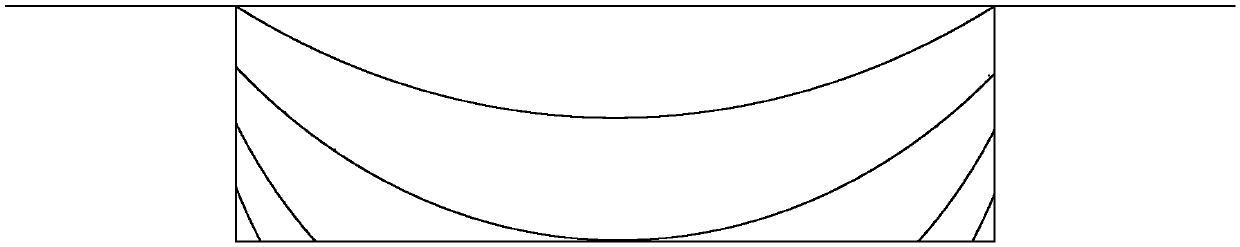
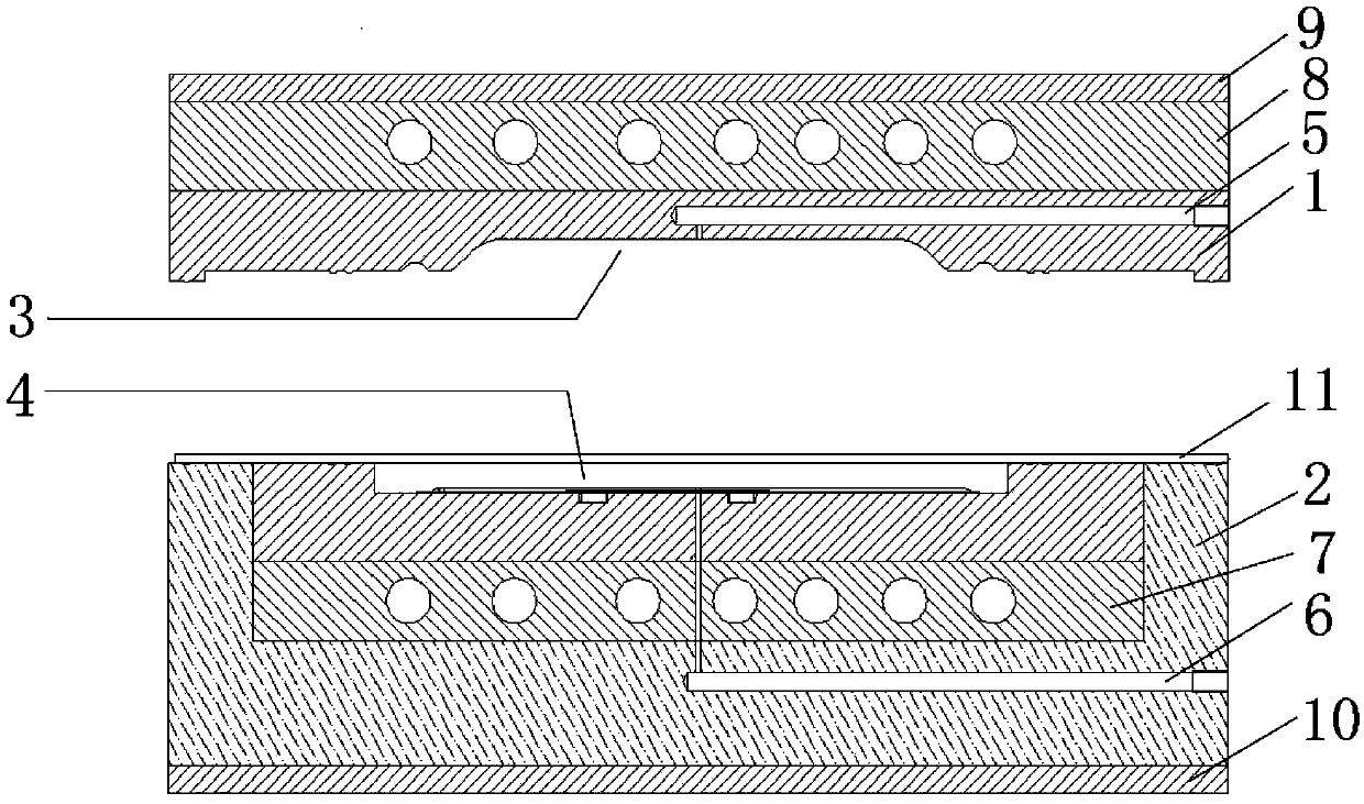
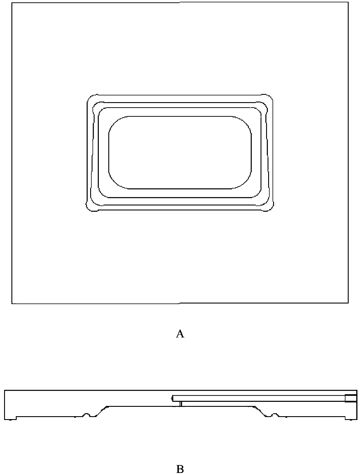
[0056] reference figure 2 with image 3 Optimize the design of the mold through calculation and simulation, and use the CNC lathe to manufacture the mold to realize that the amount required for the final workpiece can be preformed, and the preform cavity 3 of the upper mold 1 is designed and manufactured as image 3 The annular groove structure shown. The pre-formed structure is designed to improve the uniformity of the wall thickness of the part. When forming, the role of the annular groove is to thin the part that does not participate in the deformation after the normal superplastic forming, and increase its contribution to the uniformity of the forming After inflating downwards, the position of the plate 11 is exactly at the corner when it is pasted. Even if the pre-forming is not complete, the thickness of the pre-forming does not change, which just compensates for this deficiency and satisfies the overall wall thickness uniformity.

Embodiment 2

[0058] The following describes the molding process of using the mold described in Example 1, using 5083 aluminum alloy sheet with a thickness of 1 mm as raw materials, and adopting superplastic inflating technology to prepare a box-shaped electronic housing product.

[0059] reference figure 2 with Figure 4 , First heat the mold, and place the plate 11 on the forming cavity 4 after 350-600 degrees Celsius. With the action of a hydraulic press, the upper mold 1 and the lower mold 2 are closed and sealed, and 0.1-1 MPa gas is introduced through the lower air inlet 6 , The plate 11 is gradually deformed under the gas pressure, and finally fits with the pre-formed cavity 3 of the upper mold 1, and then 0.4-5MPa gas is introduced through the upper air inlet 5, so that the plate 11 is deformed downwards, and finally meets the forming cavity 4. Fit and take out the parts after forming.

[0060] Results: The thickness at the corners reached 0.7~0.9mm, and the thickness uniformity of the...


PUM

PropertyMeasurementUnit
Thicknessaaaaaaaaaa

Abstract

The invention discloses a super-plastic forming die and a method thereof. The super-plastic forming die comprises: an upper die, wherein the upper die is provided with a preforming die cavity having a preforming structure; and a lower die, wherein the lower die is concavely provided with a forming die cavity, the forming die cavity corresponds to the preforming die cavity to make the forming die cavity and the preforming die cavity form a closed space during the closing of the lower die and the upper die, the upper die and the lower die are provided with an upper air inlet and a lower air inlet respectively, and the upper air inlet and the lower air inlet are communicated with the closed space. The super-plastic forming die can realize the completion of a super-plastic forming technology, the completion of preforming and final forming in a same die, and instant forming after preforming, has the advantages of good integral formability, good mechanical performances, uniform product thickness, abundant product kind, simple preparation technology, short production period, low rejection rate, and low production cost, is suitable for the industrialized production, and has a wide application space and a very large market popularization value.

Description

Technical field [0001] The invention relates to the field of manufacturing technology, in particular to a superplastic forming mold and method. Background technique [0002] Superplastic molding technology, especially superplastic inflatable molding technology is a relatively new, advanced and immature technology. It has the advantages of good performance, high precision, simple process, convenient operation, etc. It saves energy while ensuring product quality. And equipment. In the prior art, large rounded box parts are formed by concave-convex die forming, hydroforming and other forming methods. However, when forming small rounded parts, there are easy breakage, inconsistent thickness uniformity of the workpiece, and reduced mechanical properties of the workpiece. Problems such as an increase in the rate of forming rejects. [0003] Therefore, the current superplastic molding technology needs further improvement. Summary of the invention [0004] The present invention aims to s...

Claims


Application Information

Patent Timeline
IPC IPC(8): B29C33/00B29C33/38B29C67/00
Inventor 孙瑞涛陈建伟谢业辉韩道顺林海欣关国新
Owner 北京超塑新技术有限公司
Why Eureka
Try Eureka