Electric worm driving mechanism of electric-control mechanical-type automatic speed changer

A technology of automatic transmission and driving mechanism, which is applied in the direction of mechanical equipment, components with teeth, transmission device control, etc. It can solve the problems of high processing cost, easy to touch the beam, and long size of gear shifting, and achieve a reasonable and compact space layout. , Not easy to get stuck, easy to process

Active Publication Date: 2013-10-23
玉柴芯蓝新能源动力科技有限公司
View PDF6 Cites 9 Cited by
  • Summary
  • Abstract
  • Description
  • Claims
  • Application Information

AI Technical Summary

Problems solved by technology

[0008] 1. The gear selection motor and the shift motor must be arranged perpendicular to each other, one of which is arranged on the top surface of the gearbox, and the other must be arranged on the side of the gearbox, which increases the width of the gearbox and is easy to touch the beam;
[0009] 2. After shifting gears, the gear shifting motor will stop rotating and no longer give torque. The vibration during the operation of the vehicle may cause the gear shifting gear to rotate, resulting in gear loss;
[0010] 3. The sliding gears are easy to get stuck and worn out;
[0011] 4. The size of the shift gear is long and the processing cost is high

Method used


Image

  • Electric worm driving mechanism of electric-control mechanical-type automatic speed changer
  • Electric worm driving mechanism of electric-control mechanical-type automatic speed changer
  • Electric worm driving mechanism of electric-control mechanical-type automatic speed changer

Examples


Embodiment Construction

[0043] In order to further illustrate the structure and function of the present invention, the present invention will be described in detail below in conjunction with the accompanying drawings and preferred embodiments, but it should be understood that the protection scope of the present invention is not limited by specific embodiments.

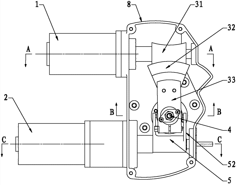
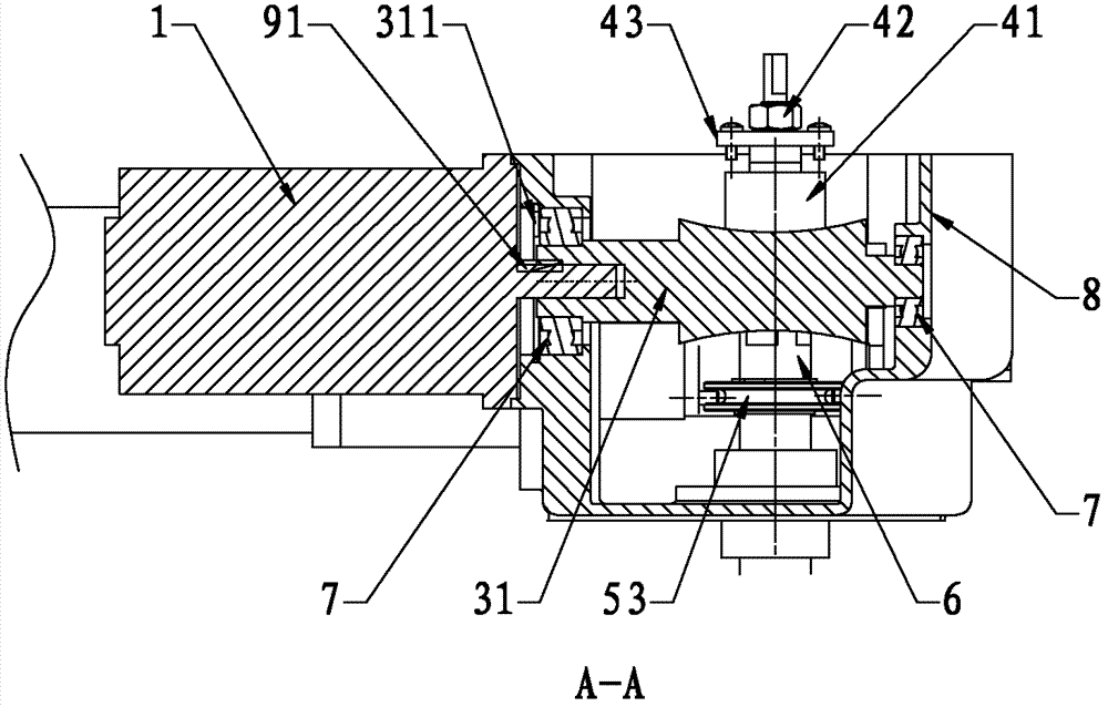
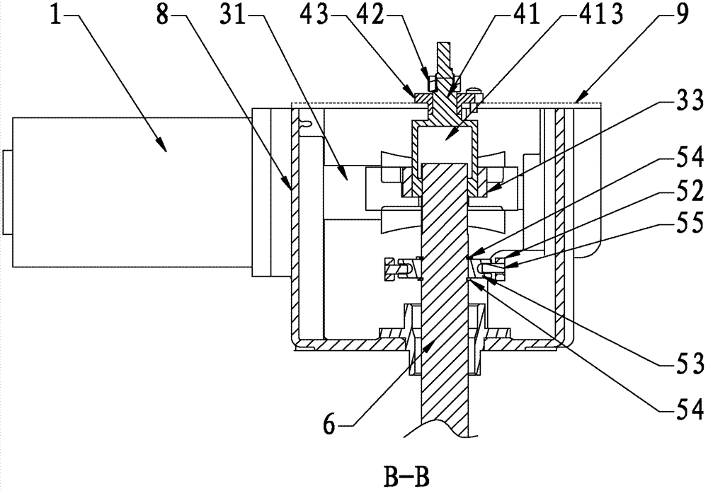
[0044] Such as Figure 1 to Figure 8 As shown, the present embodiment is an electric worm drive mechanism of an electronically controlled mechanical automatic transmission, which is arranged on the top of the gearbox, and it includes a casing, a shift shaft 6, a gear selection motor 2, a gear shift motor 1, and a gear shift assembly 4 and file selection component 5. The casing is composed of a box-shaped casing 8 and a cover plate 9; the shift motor 1 and the gear selection motor 2 are horizontally arranged on the side wall of the casing 8, and are respectively used to drive the shift shaft 6 along the circumferential direction. Rotate and m...


PUM


Abstract

The invention discloses an electric worm driving mechanism of an electric-control mechanical-type automatic speed changer. The electric worm driving mechanism is arranged at the top of a speed changing box and comprises a machine shell, a gear shifting shaft, a gear selecting motor, a gear shifting motor, a gear shifting component and a gear selecting component, the machine shell is formed by a box-shaped shell body and a cover plate, the gear shifting motor and the gear selecting motor are parallelly and horizontally arranged on the side wall of the shell body and used for driving the gear shifting shaft to circumferentially rotate and axially move respectively, and the gear shifting shaft, the gear shifting component and the gear selecting component are all arranged in the machine shell. The two motors can be arranged at the top of the speed changing box parallelly and horizontally and cannot collide a crossbeam, so that the electric worm driving mechanism is reasonable and compact in space layout; a worm transmission component has a self-locking function, so that after gears are shifted, even if the gear shifting motor stops rotating and feeding torque, the self-locking function of a worm can enable the speed changing box not to be out of gear.

Description

technical field [0001] The invention relates to the technical field of automatic transmissions, in particular to an electric worm drive mechanism of an electronically controlled mechanical automatic transmission. Background technique [0002] Automated Mechanical Transmission (AMT) is referred to as AMT. The specific situation is to use the manual transmission as the mother body, and realize the automatic operation of the shift fork and shift shaft of the manual transmission. The car is the same as the automatic transmission, so that the automation of the manual transmission is realized. AMT not only has the advantages of automatic transmission of hydraulic automatic transmission, but also retains the advantages of high efficiency, low cost, simple structure and easy manufacture of the original manual transmission gear transmission. It combines the advantages of the two, and is popular with all drivers for its unique economy, convenience, safety and comfort, and has become ...

Claims


Application Information

Patent Timeline
Patent Type & Authority Applications(China)
IPC IPC(8): F16H61/32F16H61/34F16H63/30
Inventor 周兴利吴苾曜梁锋欧阳石坤谢波
Owner 玉柴芯蓝新能源动力科技有限公司
Why Eureka
Try Eureka