Cold air flow channel distribution structure in cabinet engine room

A technology of channel distribution and cold air channel, which is applied in the direction of airflow control components and duct arrangement, which can solve the problems of local hot spots in the cabinet and the inability of uniform distribution of cold air flow.

Active Publication Date: 2013-10-23
南京华设云信息技术有限公司
View PDF4 Cites 2 Cited by
  • Summary
  • Abstract
  • Description
  • Claims
  • Application Information

AI Technical Summary

Problems solved by technology

For example, a rack-type air conditioner is placed in a rack-mounted machine room inside the cabinet. Due to the size of the air outlet of the air conditioner and the limitation of the airflow direction, the cold air in the cabinet cannot be evenly distributed to all levels in the cabinet. Even if the cold air channel is used to guide the cold air to the middle and lower parts of the cabinet, the formation of air circulation in the cabinet cannot completely solve the problem of local hot spots in the cabinet

Method used


Image

  • Cold air flow channel distribution structure in cabinet engine room
  • Cold air flow channel distribution structure in cabinet engine room

Examples


Embodiment Construction

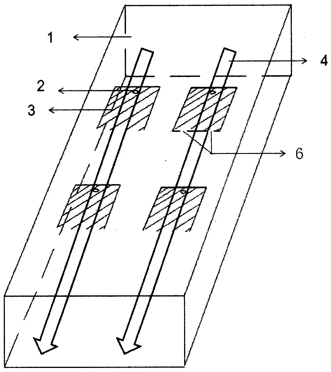
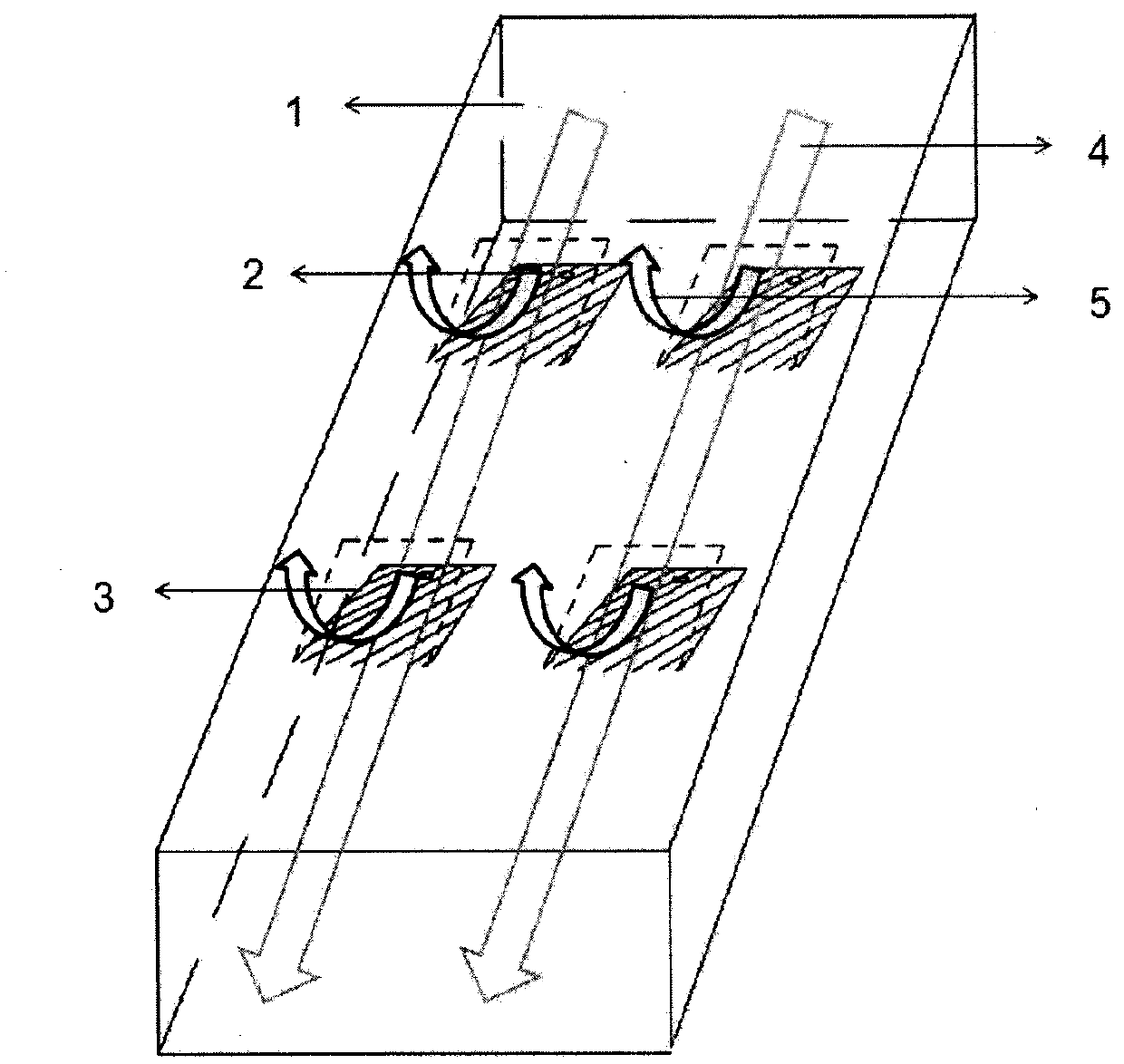
[0023] figure 1 and figure 2 A specific embodiment of the invention is shown in which figure 1 It is a structural schematic diagram when the deflector of the present invention is closed; figure 2 It is a structural schematic diagram of the adjusted deflector of the present invention.

[0024] See figure 1 and figure 2 , a cold air channel distribution structure, comprising: a cold air channel body 1; a plurality of openings, the openings are arranged on the cold air channel body 1 and communicate with the inside of the cabinet, and the positions of the openings correspond to the equipment in the cabinet; deflectors 3. The deflector 3 is arranged on the above-mentioned opening to open and close the opening. The deflector 3 includes a connection end 6 and a free end, the connection end 6 is connected to the side of the opening where the cold air flows downstream, and the free end Located on the upstream side of the opening in the direction of cold air, it can be manually...


PUM


Abstract

The invention discloses a cold air flow channel distribution structure in a cabinet engine room, which comprises a cold air channel body, at least one opening formed in the cold air channel body and communicated with the interior of a cabinet, and a flow guiding plate arranged on the opening for closing the opening, wherein the opening and equipment in the cabinet correspond in direction, and the flow guiding plate comprises a connection end and a free end, and is connected with one side edge of a cold air flow towards downstream. The work principle is sketched as follows: when being guided by the cold air channel along a pipeline direction, the air cold flow can directly reach the air outlet of the cold air channel, at the moment, after the flow guiding plate on site is adjusted by rotating a certain angle towards the interior of the cold air channel through taking the connection edge of the flow guiding plate, connected with the cold air channel, as the axial direction, the direction of the cold air flow in the linear direction of the cold air flow in the cold air channel is changed to be guided out of the cold air channel, and the local heat points in vicinity of the flow guiding plates are removed.

Description

technical field [0001] The invention belongs to the field of distribution of cold air flow passages in a computer room, and in particular relates to a distribution structure of cold air flow passages in a cabinet type computer room. Background technique [0002] The cabinet-type computer room is a kind of computer room that condenses the dust-proof, power environment monitoring system, intelligent alarm system, fire protection system, lightning protection and grounding system in the traditional room-level computer room into a standard rack-mounted cabinet. An emerging product, it is popular in the construction of small and medium computer rooms because of its small footprint, low cost, and complete functions. However, due to the small size of the cabinet-type computer room and the compact placement of internal equipment, etc., the side air supply method is generally used for the distribution of cold and hot aisles to dissipate heat for the equipment in the cabinet. For exam...

Claims


Application Information

Patent Timeline
IPC IPC(8): F24F13/02F24F13/08
Inventor 钟亚呋王瑞京吴新龙常平华
Owner 南京华设云信息技术有限公司
Why Eureka
Try Eureka