Supercharge Your Innovation With Domain-Expert AI Agents!

Combined-type switch cabinet

A switch cabinet and combined technology, which is applied in the direction of substation/switchgear board/panel/desk, substation/power distribution device shell, etc., can solve the problems of inconvenient operation and inconvenience, and achieve the effect of convenient installation and maintenance

Inactive Publication Date: 2013-10-23
万能亿工业科技发展(苏州)有限公司
View PDF3 Cites 0 Cited by
  • Summary
  • Abstract
  • Description
  • Claims
  • Application Information

AI Technical Summary

Problems solved by technology

[0002] For ordinary switch cabinets, when installing internal cables and components, installers need to complete the installation in a small space inside the cabinet, which is very inconvenient and not easy to operate during maintenance

Method used


Image

  • Combined-type switch cabinet
  • Combined-type switch cabinet

Examples


Embodiment Construction

[0010] The preferred technical solutions of the present invention will be described in detail below in conjunction with the accompanying drawings.

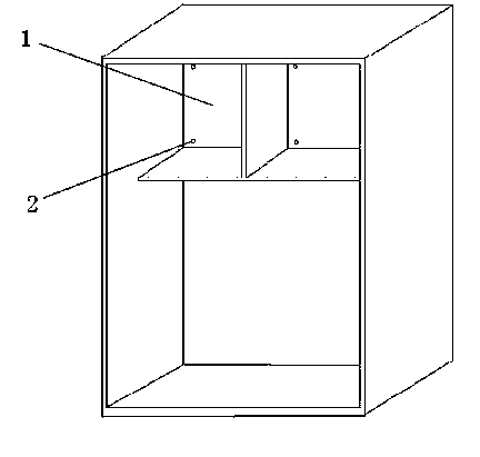
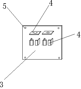
[0011] As shown in the figure, a combined switch cabinet includes an inner wall 1 of the switch cabinet. The plate 3 is provided with a card support device 4 and an installation through hole 5 corresponding to the screw hole 2 .

[0012] The card support device 4 is suitable for the installation and clamping of various cables and components inside the switch cabinet. The plate 3 is installed on the inner wall 1 of the switch cabinet, and then fixed on the screw hole 2 through the installation through hole 5 with bolts.


PUM


Abstract

The invention discloses a combined-type switch cabinet which comprises a switch cabinet inner wall. Screw holes are formed in the switch cabinet inner wall. An inner wall plate matched with the switch cabinet inner wall is arranged. A clamping supporting device and installation through holes matched with the screw holes are arranged on the inner wall plate. Compared with the prior art, the combined-type switch cabinet has the advantages that the inner wall plate can be installed inside the switch cabinet after the installation of a component or a cable on the inner wall plate is completed, and the internal installation of the switch cabinet is facilitated.

Description

technical field [0001] The invention relates to a combined switch cabinet. Background technique [0002] For ordinary switch cabinets, when installing internal cables and components, installers need to complete the installation in a small space inside the cabinet, which is very inconvenient and not easy to operate during maintenance. Contents of the invention [0003] The technical problem to be solved by the present invention is to provide a switchgear that facilitates installation of internal equipment in view of the above-mentioned deficiencies in the prior art. [0004] In order to solve the problems of the technologies described above, the technical solution adopted in the present invention is: [0005] A combined switchgear, including the inner wall of the switchgear, is characterized in that: screw holes are set on the inner wall of the switchgear, and an inner wall plate matched with the inner wall of the switchgear is set, and the inner wall plate is provided wit...

Claims


Application Information

Patent Timeline
Patent Type & Authority Applications(China)
IPC IPC(8): H02B1/26H02B1/04
Inventor 李春林
Owner 万能亿工业科技发展(苏州)有限公司
Features
  • R&D
  • Intellectual Property
  • Life Sciences
  • Materials
  • Tech Scout
  • Unparalleled Data Quality
  • Higher Quality Content
  • 60% Fewer Hallucinations
Learn More