Illuminating system capable of being controlled by any remote control

A lighting system and remote control technology, applied in the field of lighting systems, can solve the problems of inconvenient storage, inconvenient use, waste of resources, etc., and achieve the effects of saving resources, saving costs, and solving the inconvenience of switching

Inactive Publication Date: 2013-10-23
耿波
View PDF5 Cites 2 Cited by
  • Summary
  • Abstract
  • Description
  • Claims
  • Application Information

AI Technical Summary

Problems solved by technology

[0004] The technical problem to be solved by the present invention is to provide a lighting system that can be controlled by any remote control, aiming at the problems of inconvenient use and waste of resources and inconvenient storage when equipped with a special remote control.
Really realize any remote control

Method used


Image

  • Illuminating system capable of being controlled by any remote control
  • Illuminating system capable of being controlled by any remote control
  • Illuminating system capable of being controlled by any remote control

Examples


Embodiment Construction

[0021] The present invention will be further described below in conjunction with the accompanying drawings.

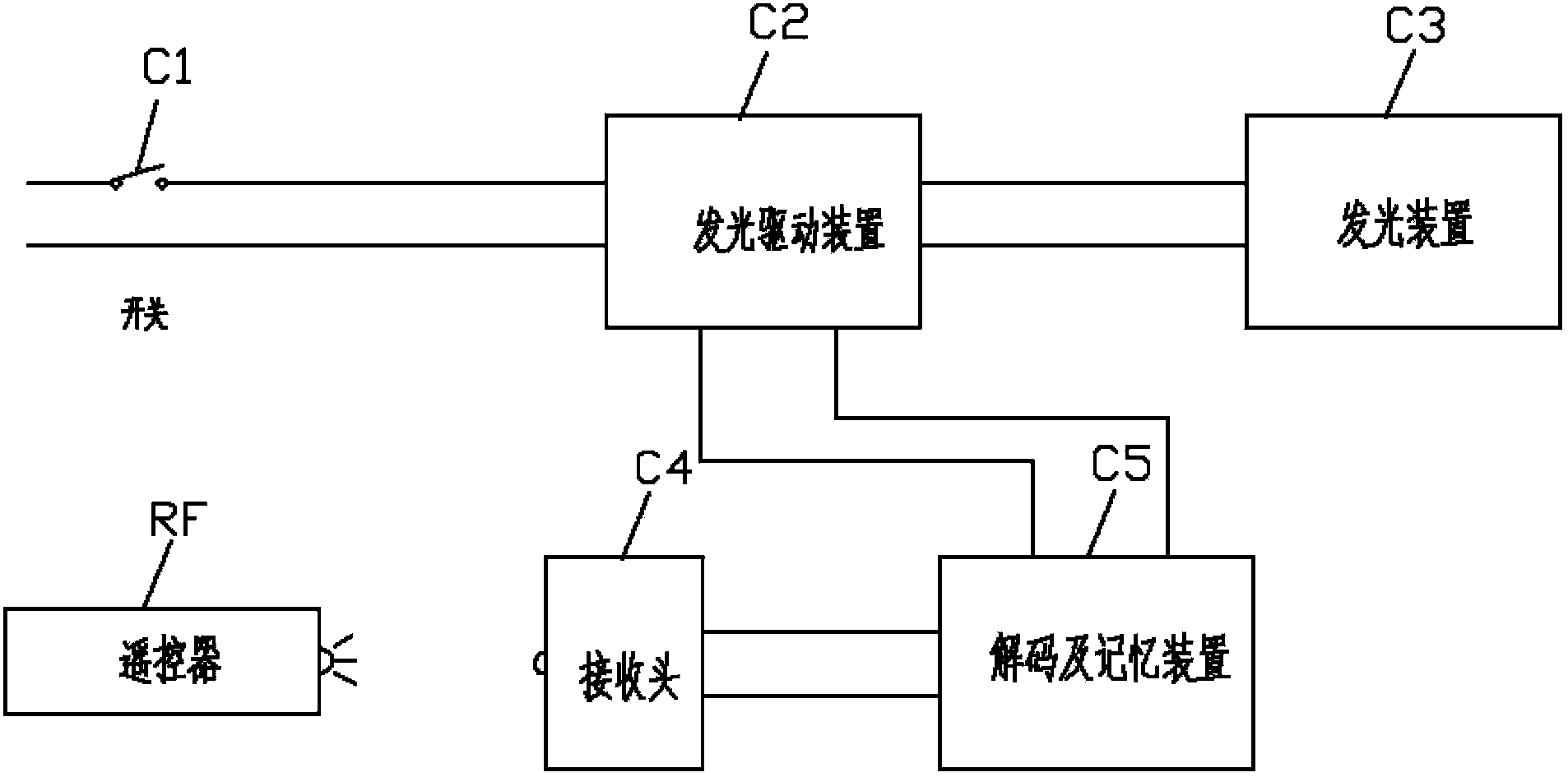
[0022] Such as Figure 1 to Figure 3 , a lighting system that can be controlled by any remote controller, which is characterized in that it includes a switch C1, a light-emitting drive device C2, a light-emitting device C3, a receiving head C4, and a decoding and memory device C5. The alternating current passes through the output terminal of the switch C1 and the light-emitting device The power input terminal of the driving device C2 is connected, the signal output terminal of the receiving head C4 is connected to the signal input terminal of the decoding and memory device C5, the signal output terminal of the decoding and memory device C5 is connected to the control signal terminal of the light-emitting drive device C2, and the light-emitting drive device The power output end of C2 is connected with the light emitting device C3.

[0023] The receiving head C4 can rec...


PUM


Abstract

An illuminating system capable of being controlled by any remote control is characterized by comprising a switch (C1), a light emission driving device (C2), a light emitting device (C3), a receiving head (C4) and a decoding and memory device (C5), an alternating current is connected with the power source input end of the light emission driving device (C2) through the output end of the switch (C1), the signal output end of the receiving head (C4) is connected with the signal input end of the decoding and memory device (C5), the signal output end of the decoding and memory device (C5) is connected with the control signal end of the light emission driving device (C2), and the power source output end of the light emission driving device (C2) is connected with the light emitting device (C3). By means of the illuminating system, a special remote control is not required for an illuminating device. Opening, closing and light adjustment of the illuminating system can be controlled through any remote control. A user can use a key, not used frequently, of the remote control to control the illuminating device by learning and remembering the coding of the remote control, and controlling by any remote control can be achieved really.

Description

Technical field [0001] The patent of this invention relates to a lighting system that can be controlled by any remote control (remote control for TV, air conditioner, etc.). And memorize the code of the remote control to realize the use of specific keys on the remote control to control the lighting system. Background technique [0002] Traditional lighting systems are usually divided into two categories in terms of control methods, one is the general category, and this type of lighting system controls the switching of the lighting system through switches. This control method also includes a switch that can realize the dimming function by adjusting the voltage. This lighting system usually has great limitations: first, this system can only be turned on and off by manipulating a switch. In some occasions, the switch is far away from the light, and it is inconvenient to control at night. Secondly, the dimming device and the switch are together, and the operation is inconveni...

Claims


Application Information

Patent Timeline
Patent Type & Authority Applications(China)
IPC IPC(8): H05B37/02
Inventor 耿波
Owner 耿波
Why Eureka
Try Eureka