
Transmission wheel arrangement

A transmission gear and wheel hub technology, which is applied to transmission parts, hoisting devices, portable lifting devices, etc., can solve the problem of shortening the structural length of transmission gears, and achieve the effect of improving radial support

Active Publication Date: 2013-10-30
GM GLOBAL TECH OPERATIONS LLC
View PDF6 Cites 4 Cited by
  • Summary
  • Abstract
  • Description
  • Claims
  • Application Information

AI Technical Summary

Problems solved by technology

This results in a shorter structural length of the drive gear in the area of ​​the hub

Method used


Image

  • Transmission wheel arrangement
  • Transmission wheel arrangement
  • Transmission wheel arrangement

Examples


Embodiment Construction

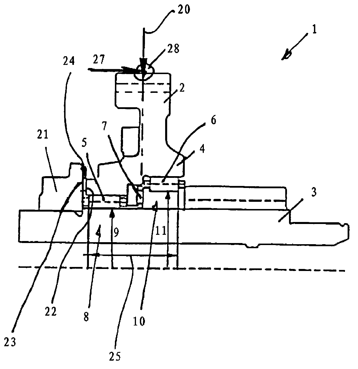
[0022] figure 1 A half-side partial sectional view of the transmission gear unit 1 with the transmission gear 2 and the shaft 3 is shown. In this case, a part of the transmission gear, which can also be referred to as a shift gear, is arranged rotatably on the shaft 3 . The transfer gear 2 has a radially outer region with gear teeth and a radially inner region also referred to as hub 4 . Preferably two radial bearings 5 ​​, 6 and an axial bearing 7 are arranged between the hub 4 of the drive gear 2 and the shaft 3 . here figure 1 It can be seen that the two radial bearings 5 ​​, 6 and the axial bearing 7 are arranged radially between the hub 4 of the drive gear 2 and the shaft 3 . In another embodiment, as a variant, more than two radial bearings can also be arranged.

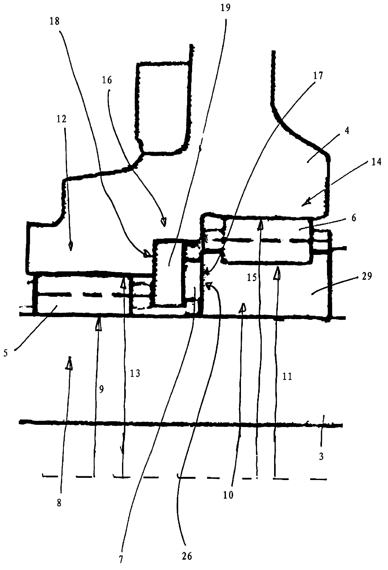
[0023] exist figure 1 and figure 2 In the illustrated embodiment, the axial bearing 7 is arranged axially between the two radial bearings 5 ​​and 6 .

[0024] exist figure 1 and figure 2 It can be se...


PUM


Abstract

The invention discloses a transmission wheel arrangement 1 comprising a transmission wheel 2 and a shaft 3 with a bearing inner ring when necessary, wherein the transmission wheel 2 is rotatably arranged on the shaft 3, at least one radial bearing 5, 6 and at least one axial bearing 7 are arranged between a hub 4 or the transmission wheel 2 and the shaft 3 or the bearing inner ring 29 along the radial direction to support the transmission wheel 2.

Description

technical field [0001] The invention relates to a transmission gear unit for transmitting torque in a transmission mechanism. Background technique [0002] Transmission gears are provided in transmissions as well as in vehicle transmissions or transmissions in order to be able to transmit torque from one shaft to the other. Such transmission gears, sometimes also referred to as shift gears, are mounted in a rotationally fixed manner on a shaft, in which radial and axial bearing arrangements are usually provided in order to position and mount the transmission gear permanently and functionally reliably. [0003] In the known transmission gearing, the transmission gear on the shaft is supported radially between the hub of the transmission gear and the shaft by means of radial bearings, wherein an axial bearing is arranged laterally adjacent to the transmission gear hub, The axial bearing acts as an axial support between the drive gear and the shaft shoulder of the shaft. [0...

Claims


Application Information

Patent Timeline
Patent Type & Authority Applications(China)
IPC IPC(8): F16H57/023F16H55/17F16C3/02
CPCF16H57/022F16H57/0031F16C19/54F16C2240/80F16C19/381F16C2361/61F16C19/505
Inventor E.沃尔夫
Owner GM GLOBAL TECH OPERATIONS LLC
Learn More