

Stator element and high-vacuum pump
A high vacuum pump and rotor element technology, applied in pump elements, pumps, axial flow pumps, etc., can solve problems such as flow reduction, improve flow, and promote pumping.
- Summary
- Abstract
- Description
- Claims
- Application Information
AI Technical Summary
Problems solved by technology
Method used
Image

Examples
Embodiment Construction
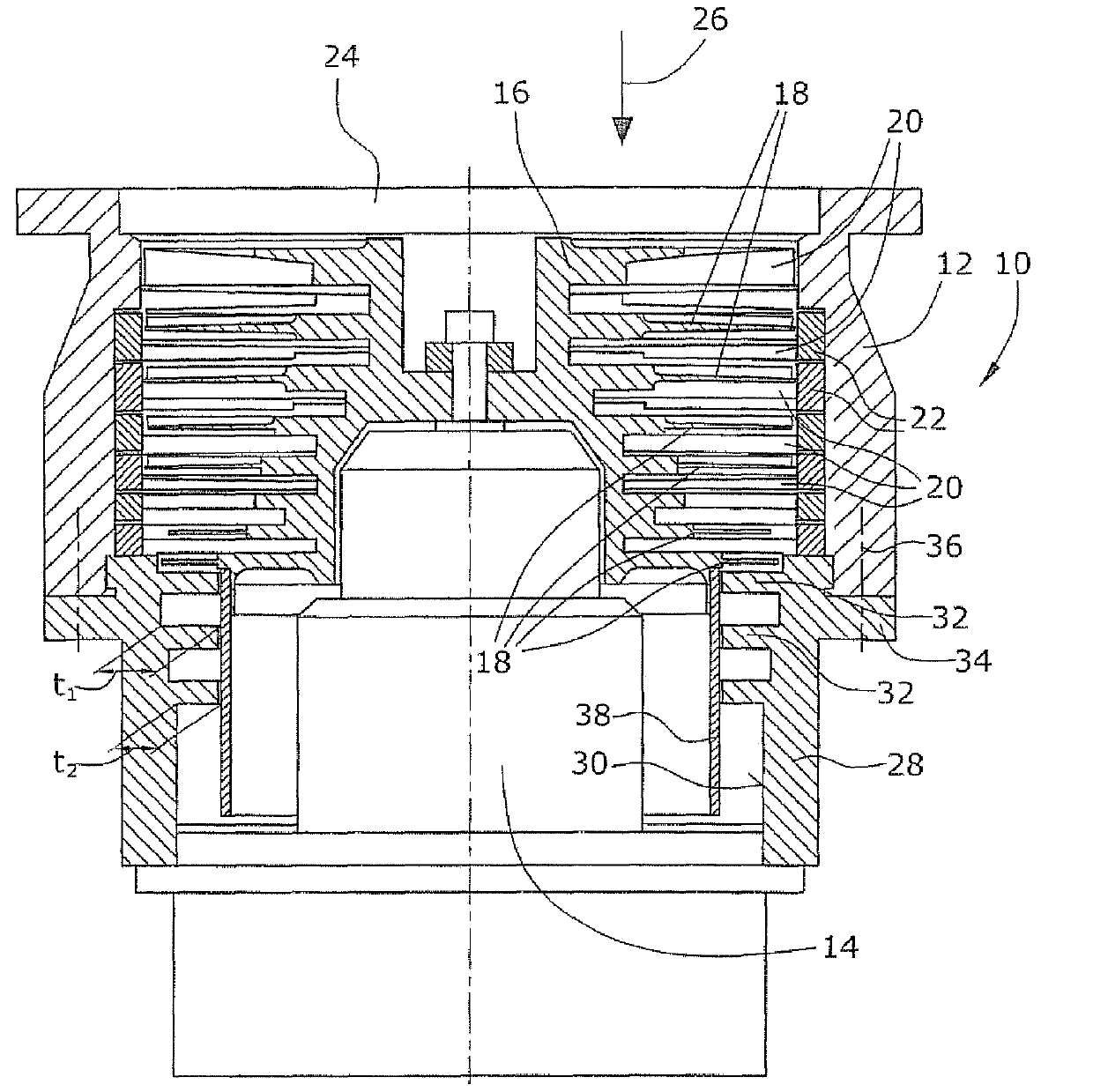
[0020] In the illustrated exemplary embodiment, the high vacuum pump has a turbomolecular pump 10 . The turbomolecular pump 10 has a rotor 16 arranged on bearings 14 in a housing 12 . The rotor 16 has a plurality of rotor elements 18 each having a plurality of rotor blades. Arranged between the rotor elements 18 are stator elements 20 which are fixed in the housing 12 via a stator ring 22 . The gas is conveyed via the pump inlet 24 in the conveying direction 26 by means of the turbomolecular pump 10 .
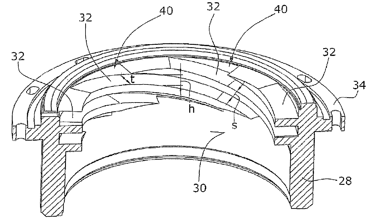
[0021] A housing element 28 is connected to the housing 12 of the turbomolecular pump 10 . The housing element 28 has stator webs 32 on its inner side 30 . The stator web 32 is arranged directly adjacent to the last rotor element in the conveying direction 26 such that no further intermediate elements, in particular no stator elements, are provided between the last rotor element 18 and the stator web 32 .
[0022] A cylindrical rotor hub 38 is fixedly connected to the last ...
PUM
| Property | Measurement | Unit |
|---|---|---|
| Depth | aaaaa | aaaaa |
Abstract
Description
Claims
Application Information