
Method for calculating main line phase difference of urban traffic signal control system

A technology of traffic signal and control system, applied in the field of phase difference calculation of main line of urban traffic signal control system, can solve the problems of increasing social unrest, noise pollution, endangering human health, etc. Effect

Inactive Publication Date: 2019-03-19
SHANDONG XINGZHI INTELLIGENT TRANSPORTATION TECH CO LTD
View PDF9 Cites 0 Cited by
  • Summary
  • Abstract
  • Description
  • Claims
  • Application Information

AI Technical Summary

Problems solved by technology

Traffic congestion increases people's travel time and costs. Air pollution and noise pollution damage the urban environment, seriously affect residents' rest, education, and cultural activities, and endanger human health. The increase in traffic accidents has caused a large number of casualties and high direct costs. and indirect economic losses, increasing social instability and restricting the further development of the city

Method used


Image

  • Method for calculating main line phase difference of urban traffic signal control system
  • Method for calculating main line phase difference of urban traffic signal control system
  • Method for calculating main line phase difference of urban traffic signal control system

Examples


Embodiment 1

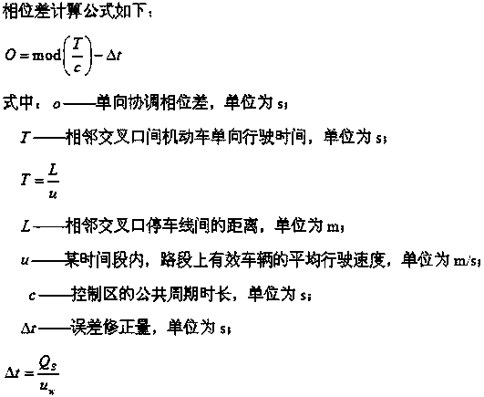
[0047] A method for calculating the phase difference of a main line of an urban traffic signal control system according to the present invention,

[0048] The phase difference calculation formula is as follows:

[0049]

[0050] In the formula: o—one-way coordination phase difference, the unit is s;

[0051] T—one-way travel time of motor vehicles between adjacent intersections, in s;

[0052]

[0053] L——the distance between the stop lines at adjacent intersections, in m;

[0054] u——In a certain period of time, the average driving speed of valid vehicles on the road section, the unit is m / s;

[0055] c——the public cycle duration of the control area, the unit is s;

[0056] Δt——error correction amount, unit is s;

[0057]

[0058] In the formula: t k ——The time when the traffic wave reaches the end of the queue, the unit is s;

[0059] Q S ——The queue length during the red light period, in m,

[0060] ——Evaluate the saturated headway spacing, that is, the...

Embodiment 2

[0071] In this embodiment, it is possible to check whether the phase difference setting is appropriate and correct by using the calculation of the number of queuing vehicles to coordinate the phase difference during the red light period. If the number of queuing vehicles N 12 If it does not meet the expected value, you need to adjust the phase difference.

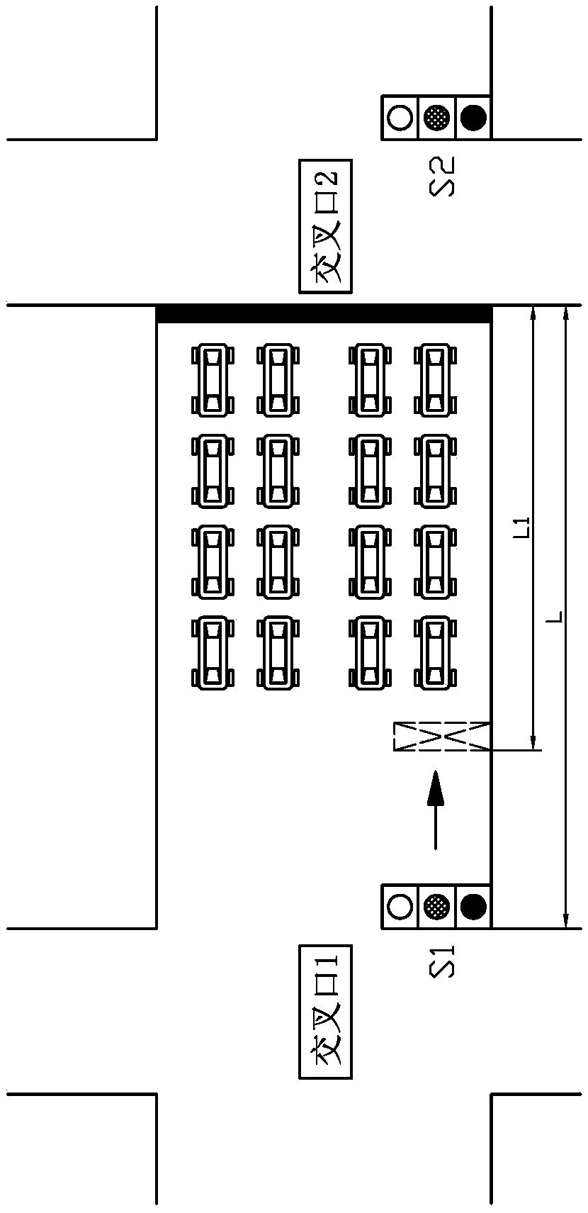
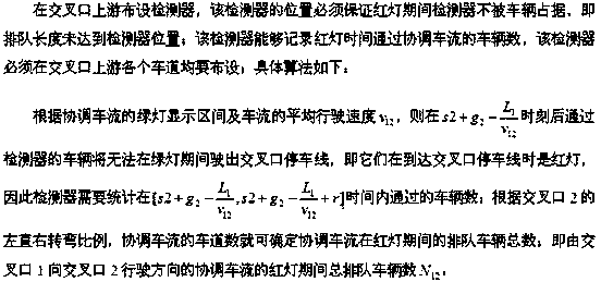
[0072] A detector is arranged upstream of the intersection, and the position of the detector must ensure that the detector is not occupied by vehicles during the red light period, that is, the queue length does not reach the position of the detector; the detector can record the number of vehicles passing the coordinated traffic flow during the red light time, and the Detectors must be deployed in all lanes upstream of the intersection, such as figure 1 shown. The specific algorithm is as follows:

[0073] According to the green light display section of the coordinated traffic flow and the average driving speed v of the ...


PUM


Abstract

The invention discloses a method for calculating a main line phase difference of an urban traffic signal control system, and belongs to the technical field of urban traffic intelligent control. The method for calculating the main line phase difference of the urban traffic signal control system is characterized in that the calculation formula of the phase difference is shown in the description. Thecalculation of the number of vehicles queued to coordinate the phase difference is used during the red light period to verify whether the phase difference setting is appropriate or correct, the phasedifference needs to be adjusted if the number of vehicles queued (shown in the description) does not meet an expected value. The method for calculating the main line phase difference of the urban traffic signal control system can accurately calculate the main line phase difference and check whether the main line phase difference is appropriate or correct. By using the accurate calculation and regulation of the main line phase difference, the main line traffic can be kept smooth, and the traffic condition of a nearby area can be optimized.

Description

technical field [0001] The invention belongs to the technical field of urban traffic intelligent control, and in particular relates to a method for calculating the phase difference of main lines of an urban traffic signal control system. Background technique [0002] As a basic part of the social economy and material structure, the development level of the transportation system is one of the important symbols of the country's prosperity. The rapid development of the transportation industry can organize production more effectively, arrange life, improve the effective operation of urban passenger and cargo flow, and promote urban economic development. However, modern means of transportation have also brought various traffic problems to cities. For nearly half a century, traffic congestion, road blockages, frequent traffic accidents, and serious environmental pollution have greatly plagued large cities around the world. Traffic congestion increases people's travel time and cos...

Claims


Application Information

Patent Timeline
IPC IPC(8): G08G1/07G08G1/08
CPCG08G1/07G08G1/08
Inventor 马成刚李江波刘红刚刘春雷刘西营邓赞丰
Owner SHANDONG XINGZHI INTELLIGENT TRANSPORTATION TECH CO LTD
Learn More