

Full-mechanical drive feeding device of reactor with high solid concentration
A high solid concentration, reactor technology, applied in the field of feeding devices, can solve problems such as poor valve sealing, inability to sample, and collect too much liquid, and achieve the effect of avoiding the stage of raw material slipping
- Summary
- Abstract
- Description
- Claims
- Application Information
AI Technical Summary
Problems solved by technology
Method used
Image

Examples
Embodiment 1
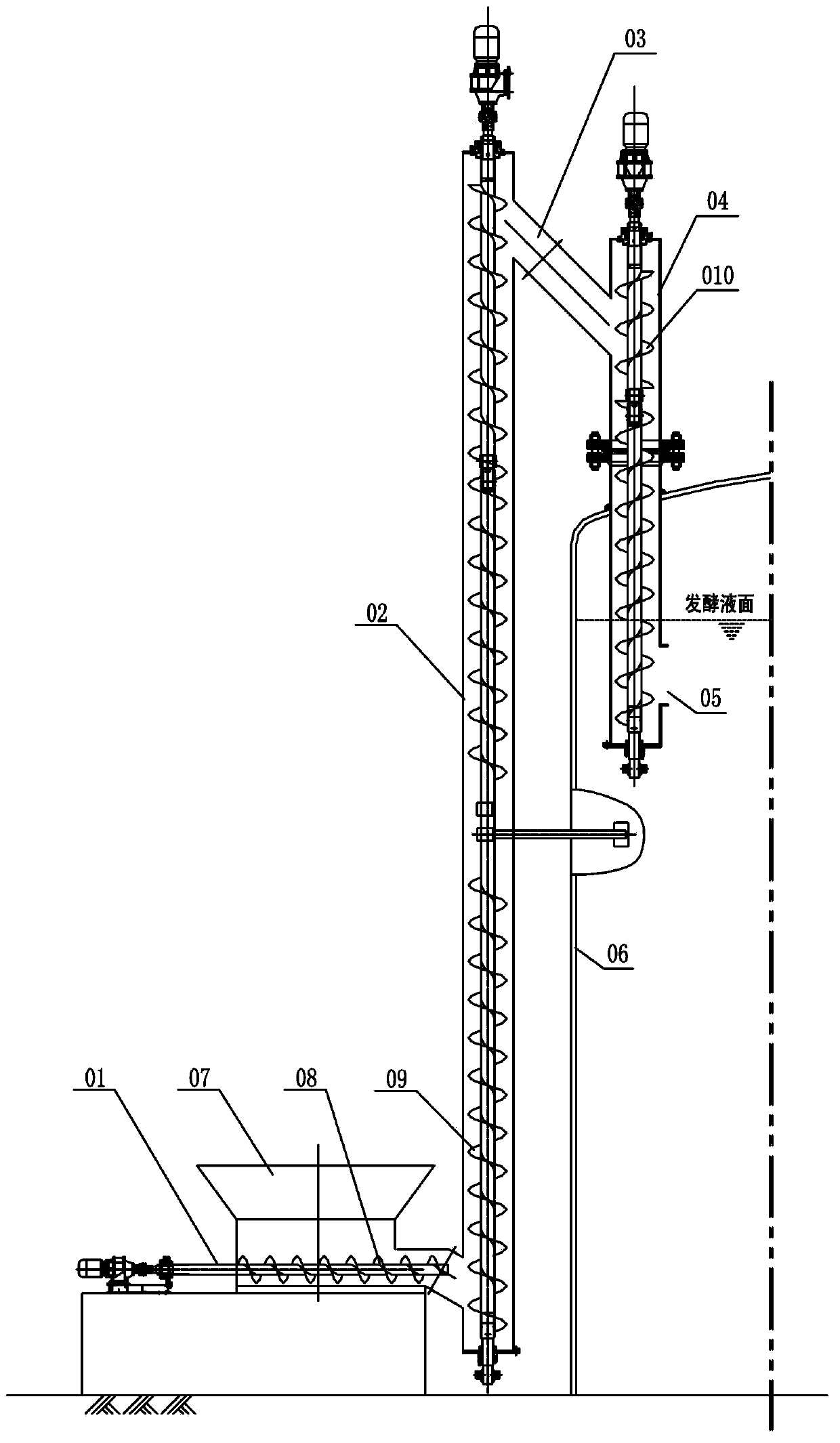
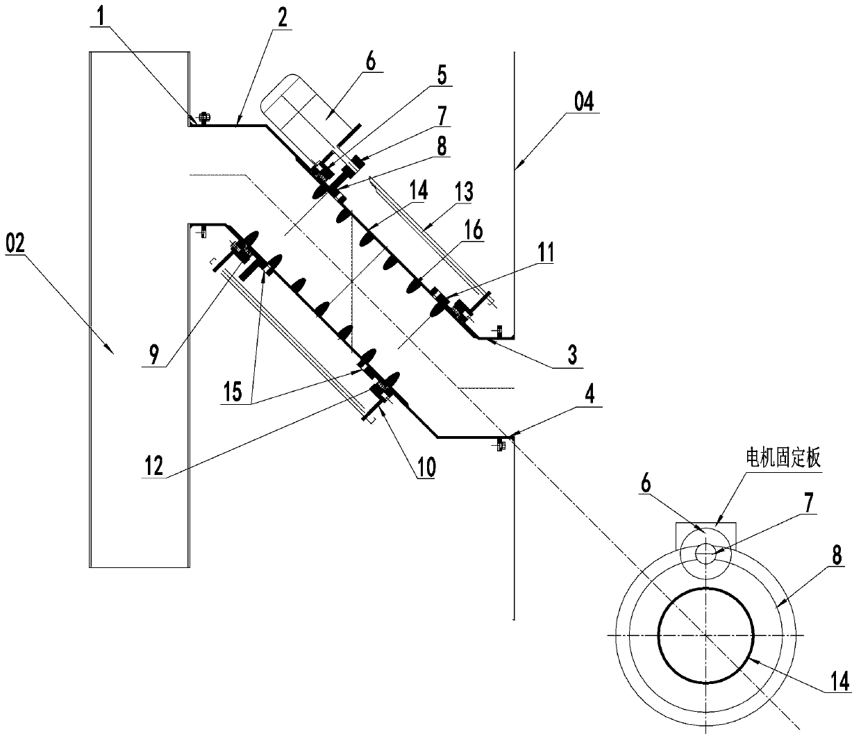
[0027] see figure 1 and figure 2 As mentioned above, the fully mechanically driven feeding and sampling device for the high solid concentration reactor includes a fully mechanically driven feeding device and a fully mechanically driven sampling device. The fully mechanically driven feeding device in this embodiment mainly includes: Horizontal screw feeder 01 for horizontally conveying materials, vertical screw feeder 02 for lifting materials upward, vertical screw feeder 04 for feeding into anaerobic reactor 06, and connecting vertical screw feeder 02 The key mechanical conveying equipment at the upper end and the upper end of the vertical screw feeder 04—the drum screw feeder 03; the fully mechanically driven sampling device is installed on the wall of the anaerobic reactor 06 and the material to be sampled in the anaerobic reactor 06 Liquid layer position, it comprises piston cylinder 17, and piston cylinder 17 part is in anaerobic reactor 06 and has sampling port 18, and ...
PUM
 Abstract
Description
Claims
Application Information