
Full-mechanical drive feeding and sampling device of reactor with high solid concentration

A high solid concentration, driving device technology, applied in the direction of gas production bioreactors, biological material sampling methods, etc., can solve the problems of collecting more liquids, less solids, and not being able to reflect the true composition of the sampling layer

Active Publication Date: 2015-02-04
GUANGZHOU INST OF ENERGY CONVERSION - CHINESE ACAD OF SCI
View PDF9 Cites 0 Cited by
  • Summary
  • Abstract
  • Description
  • Claims
  • Application Information

AI Technical Summary

Problems solved by technology

However, when this method is applied in an anaerobic fermentation system with high solid concentration of TS ≥ 8% or even higher, there will be the following disadvantages: ① the collected liquid is too much and the solid is less, which cannot reflect the real composition of the sampling layer; ② valves (commonly used are Butterfly valve and gate valve) are very easy to rust, which makes the operation more difficult, and even sampling is impossible, and the corroded valve is easy to cause poor sealing; ③The fluidity of high solid concentration materials in the pipeline is poor, and it is easy to form temporary retention and may block the pipeline ; ④ Difficult to control the sampling volume

Method used


Image

  • Full-mechanical drive feeding and sampling device of reactor with high solid concentration
  • Full-mechanical drive feeding and sampling device of reactor with high solid concentration
  • Full-mechanical drive feeding and sampling device of reactor with high solid concentration

Examples


Embodiment 1

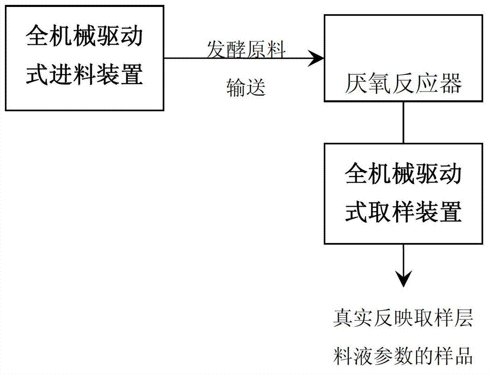
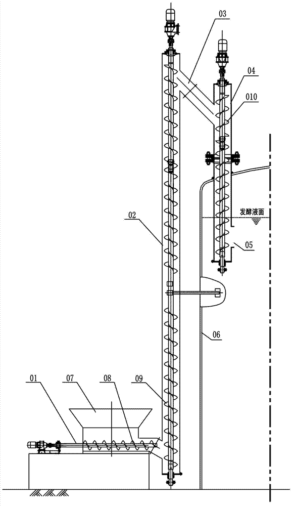
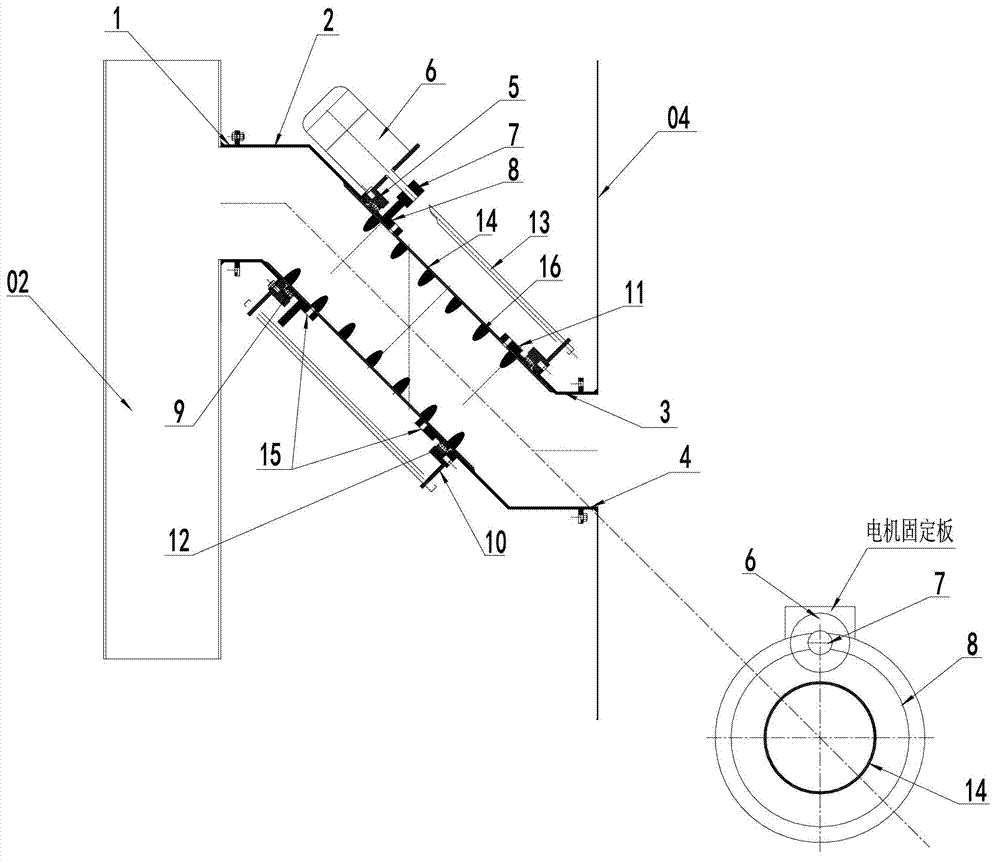
[0027] see figure 1 and figure 2 As mentioned above, the fully mechanically driven feeding and sampling device for the high solid concentration reactor includes a fully mechanically driven feeding device and a fully mechanically driven sampling device. The fully mechanically driven feeding device in this embodiment mainly includes: Horizontal screw feeder 01 for horizontally conveying materials, vertical screw feeder 02 for lifting materials upward, vertical screw feeder 04 for feeding into anaerobic reactor 06, and connecting vertical screw feeder 02 The key mechanical conveying equipment at the upper end and the upper end of the vertical screw feeder 04—the drum screw feeder 03; the fully mechanically driven sampling device is installed on the wall of the anaerobic reactor 06 and the material to be sampled in the anaerobic reactor 06 Liquid layer position, it comprises piston cylinder 17, and piston cylinder 17 part is in anaerobic reactor 06 and has sampling port 18, and ...


PUM


Abstract

The invention discloses a full-mechanical drive feeding and sampling device of a reactor with high solid concentration. The feeding device comprises a horizontal spiral conveyor, a longitudinal spiral conveyor, a longitudinal spiral feeder and a drum spiral conveyor, wherein the horizontal spiral conveyor is used for conveying materials horizontally; the longitudinal spiral conveyor is used for lifting the materials upwards; the longitudinal spiral feeder is used for feeding the materials into an anaerobic reactor; the drum spiral conveyor is connected at the upper ends of the longitudinal spiral conveyor and the longitudinal spiral feeder; the sampling device is installed in the position, on the wall surface of the anaerobic reactor, of a feed liquid layer needing sampling in the anaerobic reactor, and comprises a piston cylinder; the piston cylinder is provided with a sampling hole and a sample outlet; a first piston and a second piston are arranged in the piston cylinder; a sampling cavity is formed between the first and second pistons; and the sampling device also comprises a driving system used for driving the first and second pistons to move in the piston cylinder together. The feeding and sampling device avoids the following problems caused by sampling anaerobic fermentation materials with high solid concentration by utilizing hydraulic pressure and gravity: the liquid is more and the solid is less; the sampling quantity is not easy to control; pipelines are blocked; and valves are not easy to open, close or seal after being rusted.

Description

technical field [0001] The present invention relates to a device for feeding and sampling, more specifically, the present invention relates to a fully mechanically driven device mainly used in anaerobic fermentation engineering and used in conjunction with high solid concentration (TS≥8%) anaerobic reactors device. Background technique [0002] Organic waste contains a large amount of organic matter, such as carbohydrates, proteins, fats, and cellulose. It is a biomass resource with a wide range of sources, large quantities, and high quality. To build large and medium-sized biogas projects——use anaerobic digestion technology to treat organic waste Material is an important means to promote the sustainable development of urban and rural economic construction and realize the dual benefits of energy and environmental protection. At present, more than 10% of organic solid waste in Europe is treated by anaerobic fermentation technology. [0003] The anaerobic reactor, including ...

Claims


Application Information

Patent Timeline
Patent Type & Authority Patents(China)
IPC IPC(8): C12M1/107C12M1/26
Inventor 甄峰袁振宏孙永明孔晓英李连华李志兵
Owner GUANGZHOU INST OF ENERGY CONVERSION - CHINESE ACAD OF SCI
Features
  • Generate Ideas
  • Intellectual Property
  • Life Sciences
  • Materials
  • Tech Scout
  • Unparalleled Data Quality
  • Higher Quality Content
  • 60% Fewer Hallucinations
Learn More