
Polarization converter and polarization conversion system

A polarization converter and polarization conversion technology, which can be used in polarization components, instruments, optics, etc., and can solve the problems of low efficiency of polarization converters and polarizers.

Active Publication Date: 2013-11-13
THE HONG KONG UNIV OF SCI & TECH
View PDF8 Cites 11 Cited by
  • Summary
  • Abstract
  • Description
  • Claims
  • Application Information

AI Technical Summary

Problems solved by technology

Conventional polarization converters and polarizers are generally inefficient if the incident light is unpolarized

Method used


Image

  • Polarization converter and polarization conversion system
  • Polarization converter and polarization conversion system
  • Polarization converter and polarization conversion system

Examples


Embodiment Construction

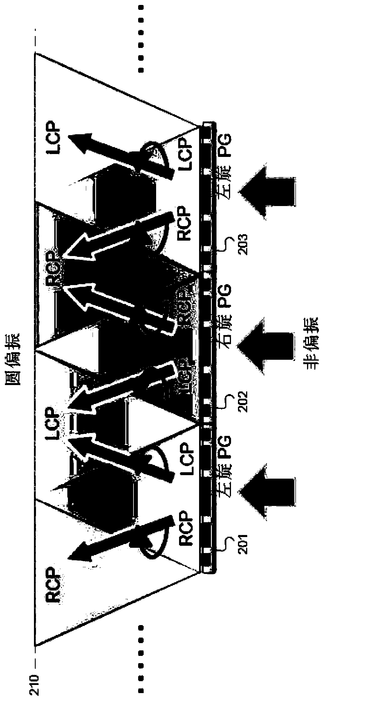
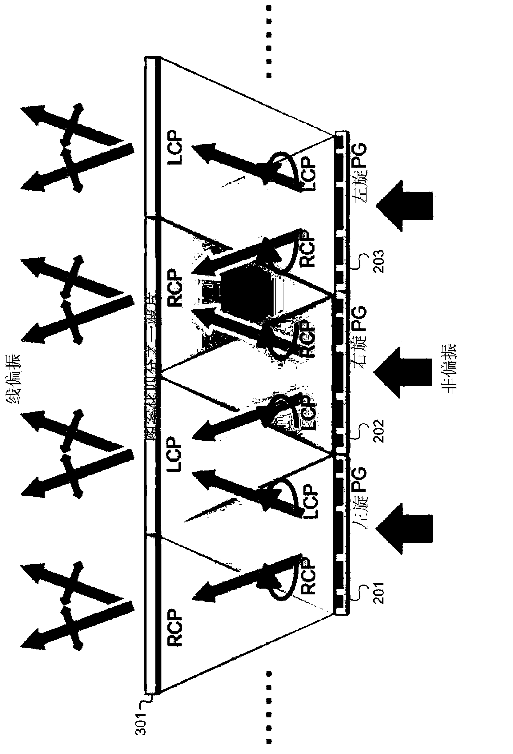
[0015] Embodiments of the present invention provide a polarization converter that converts incident unpolarized light into outgoing circularly polarized light or linearly polarized light with high efficiency. The polarization converter includes a patterned polarization grating. By using, for example, the single-step multi-domain photoalignment method described in U.S. Patent Application Serial No. 13 / 274,127, entitled "Patterned Polarization Converter," it is possible to overcome problems in the photoalignment layer and / or multi-domain on the difficulty in fabricating polarization gratings patterned into spatially varying alignments, the US Patent Application is hereby incorporated by reference in its entirety.

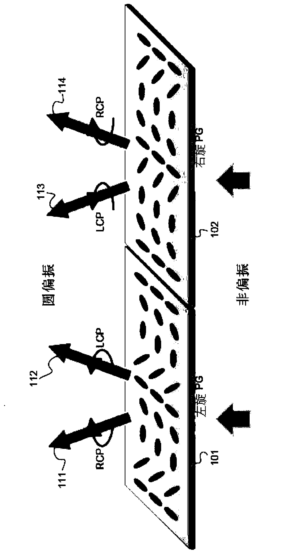
[0016] figure 1 Showing a left-handed polarization grating 101 ( figure 1 left) and right-handed polarization grating 102 ( figure 1 properties on the right). Such as figure 1 As shown, the polarization grating converts unpolarized incident light into left-handed...


PUM


Abstract

A polarization converter and polarization conversion systems are provided. The polarization converter and polarization conversion systems include a patterned polarization grating with left hand and right hand polarization grating domains. The polarization grating domains are configured to diffract incident non-polarized light into beams having left and right circular polarization states.

Description

[0001] Cross References to Related Applications [0002] This application claims priority to US Provisional Patent Application Serial No. 61 / 688,086, filed May 8, 2012, which is incorporated herein by reference. technical field [0003] The present invention relates to a polarization converter, in particular, it relates to the ability to convert incident non-polarized light into outgoing linearly polarized light or outgoing circularly polarized light with extremely high conversion efficiency. Background technique [0004] Optically controlled alignment technology can produce spatially varying liquid crystal alignment patterns on the optically controlled alignment layer, and one of the representative applications is polarization grating (PG). [0005] PG is a sinusoidal phase grating made of a retardation layer with a spatially varying optical axis. Unlike other optical gratings, PG diffracts almost all incident light into +1 and -1 diffraction orders, and other high-order a...

Claims


Application Information

Patent Timeline
IPC IPC(8): G02B5/30G02B27/28
CPCG02B27/286G02B27/285
Inventor 杜涛樊帆V·G·奇格利诺夫郭海成
Owner THE HONG KONG UNIV OF SCI & TECH
Learn More