
A phase-shifted full-bridge periodic self-protection circuit and its control method

A phase-shifting full-bridge and self-protection technology, applied in the direction of emergency protection circuit devices, electrical components, etc., can solve problems such as high cost, increased burden on DSP processors, and inability to fully close the switch tube, so as to avoid transformer bias, The effect of simple and easy circuit

Active Publication Date: 2016-06-22
SOUTH CHINA UNIV OF TECH
View PDF3 Cites 0 Cited by
  • Summary
  • Abstract
  • Description
  • Claims
  • Application Information

AI Technical Summary

Problems solved by technology

[0002] The phase-shifted full-bridge circuit is already a very mature soft-switching circuit, and it is often used as a circuit topology for medium and high-power power supplies. The four switching tubes on the bridge arm are often controlled by a TI2000 series DSP processor, through which the DSP processor can generate Time-zone PWM signal, to avoid the phenomenon of the same bridge arm straight-through on the circuit, but when there is an overcurrent, it is necessary to turn off all four switches, and the DSP processor always outputs 2 complementary PWM signals, which cannot be realized The switch tube is fully closed, which is contrary to the requirements in the case of overcurrent
In addition, the commonly used single-cycle protection control will cause transformer magnetic bias phenomenon when the system continuously over-current occurs. Although the half-cycle protection control can alleviate the magnetic bias phenomenon, it needs to add a PWM signal at the same time, which will undoubtedly increase the burden on the DSP processor. , especially for multi-machine parallel circuits, due to the limited PWM port of the DSP processor, if each single machine needs to add a PWM signal, only one DSP processor can be controlled originally, and two pieces may be needed at this time Even more, at a higher cost

Method used


Image

  • A phase-shifted full-bridge periodic self-protection circuit and its control method
  • A phase-shifted full-bridge periodic self-protection circuit and its control method
  • A phase-shifted full-bridge periodic self-protection circuit and its control method

Examples


Embodiment Construction

[0033] The implementation of the present invention will be described in further detail below in conjunction with the accompanying drawings, but the implementation and protection of the present invention are not limited thereto.

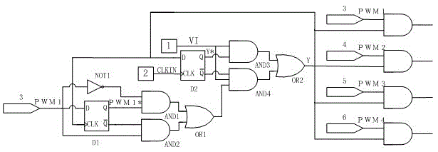
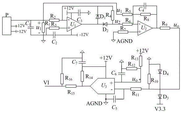
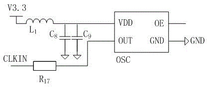
[0034] Such as figure 1As shown, a phase-shifted full-bridge cycle self-protection circuit, including: 4 PWM output terminals of DSP processor, current sampling and comparison circuit 1, active crystal oscillator circuit 2, first falling edge trigger D flip-flop D1 , the second falling edge trigger D flip-flop D2, the first double-input OR gate OR1, the second double-input OR gate OR2, the first NOT gate NOT1, the first double-input AND gate AND1, the second double-input AND gate AND2, the second Three double-input AND gate AND3, the fourth three-input AND gate AND4, the fifth double-input AND gate AND5, the sixth double-input AND gate AND6, the seventh double-input AND gate AND7, the eighth double-input AND gate AND8; The 4 PWM output terminals of t...


PUM


Abstract

The invention discloses a phase-shifted full-bridge cycle self-protection circuit and a control method thereof. The protection circuit comprises a DSP (Digital Signal Processor), a current sample and comparison circuit, an active oscillator circuit, a first falling edge-triggered D flip-flop, a second falling edge-triggered D flip-flop, a first dual input OR gate, a second dual input OR gate, a first NOT gate, a first dual input AND gate, a second dual input AND gate, a third dual input AND gate, a fourth dual input AND gate, a fifth dual input AND gate, a sixth dual input AND gate, a seventh dual input AND gate, and an eighth dual input AND gate. Four paths of input PWM (Pulse-Width Modulation) signals can be simultaneously turned to be low level when a circuit is overcurrent, so that total switch-off of a switch tube is realized, and the magnetic biasing phenomenon of a transformer cannot be generated when continuous overcurrent occurred; and meanwhile, the DSP only needs to output four paths of PWM signals, so that the utilization ratio of the DSP is improved. The cycle self-protection circuit is simple and practical, overcurrent protection is realized with least PWM signals, and the design cost is lowered.

Description

technical field [0001] The invention relates to the technical field of a phase-shifted full-bridge switching power supply, in particular to a phase-shifted full-bridge periodic self-protection circuit and a control method thereof. Background technique [0002] The phase-shifted full-bridge circuit is already a very mature soft-switching circuit, and it is often used as a circuit topology for medium and high-power power supplies. The four switching tubes on the bridge arm are often controlled by a TI2000 series DSP processor, through which the DSP processor can generate Time-zone PWM signal, to avoid the phenomenon of the same bridge arm straight-through on the circuit, but when there is an overcurrent, it is necessary to turn off all four switches, and the DSP processor always outputs 2 complementary PWM signals, which cannot be realized The switch tube is fully closed, which is contrary to the requirement in the case of overcurrent. In addition, the commonly used single-cy...

Claims


Application Information

Patent Timeline
Patent Type & Authority Patents(China)
IPC IPC(8): H02H7/12
Inventor 杜贵平朱天生
Owner SOUTH CHINA UNIV OF TECH
Learn More