
Device for melt spinning

A technology of melt spinning and equipment, which is applied in the equipment field of composite yarn

Inactive Publication Date: 2013-11-20
OERLIKON TEXTILE GMBH & CO KG
View PDF7 Cites 5 Cited by
  • Summary
  • Abstract
  • Description
  • Claims
  • Application Information

AI Technical Summary

Problems solved by technology

Therefore, although this type of equipment offers high flexibility in the production of composite yarns, it has the disadvantage of high technical equipment requirements in order to spin filament bundles in parallel

Method used


Image

  • Device for melt spinning
  • Device for melt spinning
  • Device for melt spinning

Examples


Embodiment Construction

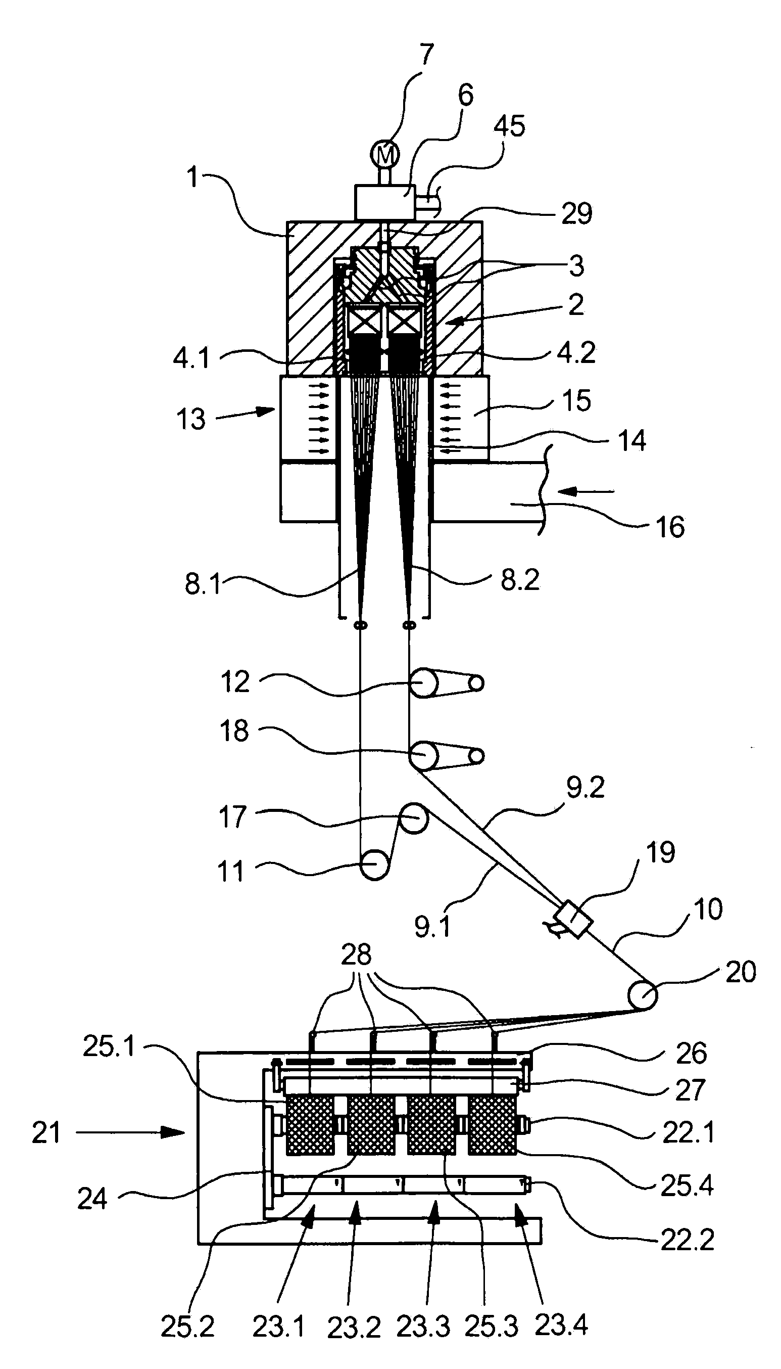
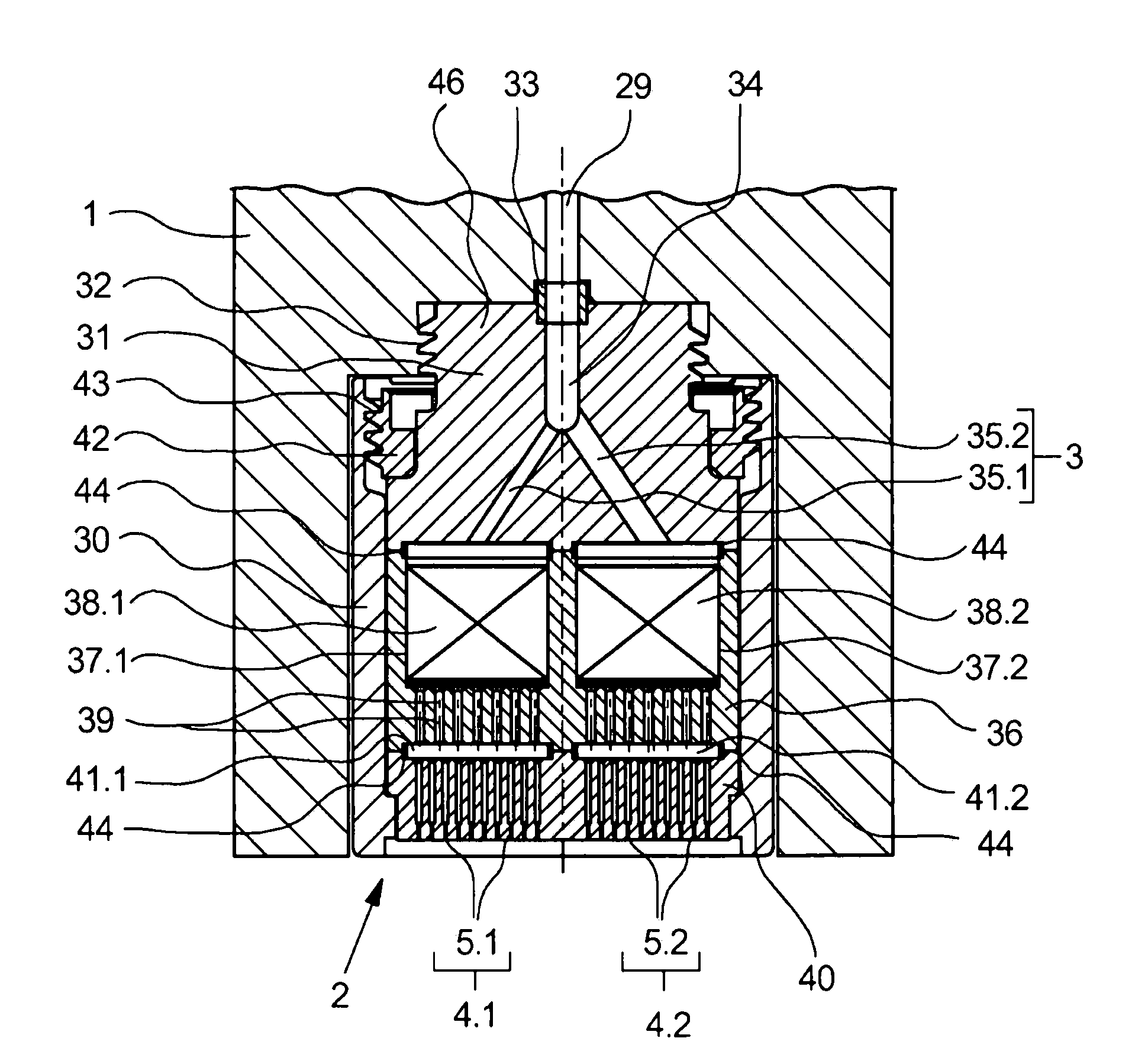
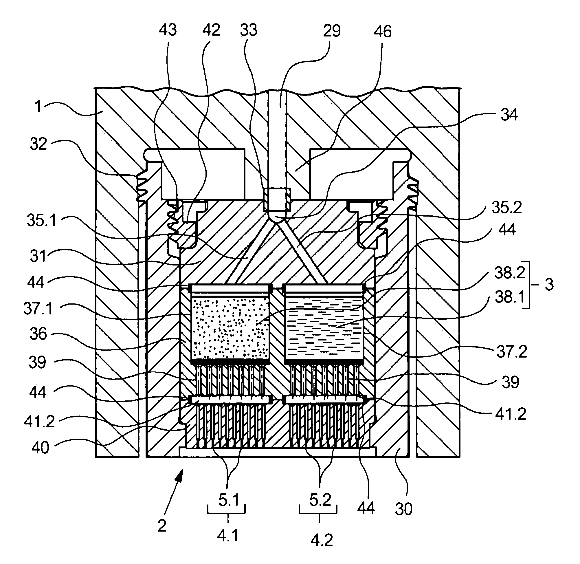
[0029] exist figure 1 , a schematic diagram of a first exemplary embodiment of an apparatus for melt spinning a composite yarn formed from a plurality of filament bundles according to the present invention is shown. An exemplary embodiment is illustrated in an operating state in which two filament bundles guided in parallel are extruded in one spinning position, stretched to form part of the filament and then Combined to form composite filaments. For this purpose, a heated nozzle support 1 is arranged in the spinning position, said nozzle support 1 supporting on the underside a spinning device in the form of a spinning nozzle arrangement 2 for extruding a plurality of filament tow. The spinning nozzle arrangement 2 has two sets of nozzle holes 4 . For this, the spinning nozzle arrangement 2 is connected to the spinning pump 6 via a melt connection 29 . On the inlet side, the spinning pump 6 is coupled via a melt inlet 45 to a melt source (not shown here), for example an ex...


PUM


Abstract

The invention relates to a device for melt spinning a composite thread comprising a plurality of filament bundles. The device comprises a plurality of spinning means for extruding a plurality of filament bundles and a plurality of drawing and stretching means by which the filament bundles can be produced as partial threads having different extensions. In order to be able to extrude a plurality of filament bundles using as little equipment as possible, according to the invention, the spinning means are formed by a spinning nozzle device having a plurality of groups of nozzle holes on a nozzle plate, wherein the spinning nozzle device comprises at least one distributing means for generating unequal volume flows from a polymer melt, by means of which the filament bundles can be extruded in parallel.

Description

Technical field [0001] The present invention relates to an apparatus for melt spinning composite yarns formed from a plurality of filament bundles. Background technique [0002] In melt spinning of synthetic yarns, multifilament yarns are usually produced which are formed from a plurality of strip-shaped filaments. The individual filaments are bundled into threads, drawn during the melt spinning process and wound onto a drum. However, such synthetic threads are not suitable for use in textiles due to their smooth structure and are therefore reprocessed during further processing in order to produce defined surface structures, such as curls. In order to obtain a structure from a thermally reprocessed synthetic thread, a composite thread formed from at least two differently drawn filament bundles is additionally produced in a melt spinning process. Therefore, it is known that the shrinkage characteristics of synthetic yarns depend on the degree of stretch. Thus, the composit...

Claims


Application Information

Patent Timeline
IPC IPC(8): D01D1/06D01D1/10D01D4/06D01D5/08
CPCD01D1/06D01D5/082D01D4/06D01D1/106
Inventor M·菲舍尔J·施特尔
Owner OERLIKON TEXTILE GMBH & CO KG
Learn More