
Method and system for communicating between a first device party and one or more other device parties

A technology of equipment and communication network, applied in transmission system, wireless communication, data exchange through path configuration, etc., can solve the problem of not knowing equipment communication, etc.

Active Publication Date: 2017-07-21
SCHNEIDER ELECTRIC IND SAS
View PDF3 Cites 0 Cited by
  • Summary
  • Abstract
  • Description
  • Claims
  • Application Information

AI Technical Summary

Problems solved by technology

However, the message is sent in the context of a network using the IP (Internet Protocol) protocol, so it does not know its IP address and cannot communicate directly with the device

Method used


Image

  • Method and system for communicating between a first device party and one or more other device parties
  • Method and system for communicating between a first device party and one or more other device parties
  • Method and system for communicating between a first device party and one or more other device parties

Examples


Embodiment Construction

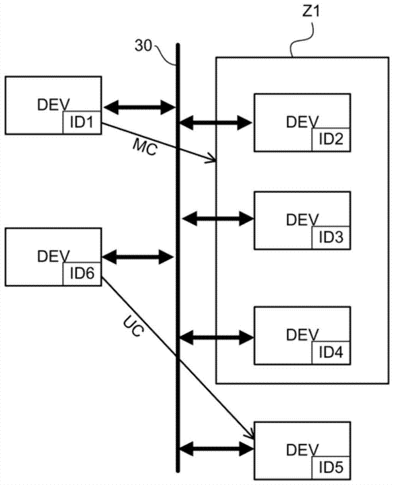
[0022] The present invention relates to a communication system comprising a number of devices DEV communicating together via a communication network 30, each device employing an identifier ID1, ID2, ID3, ID4, ID5, ID6 (hereinafter denoted by ID) so that they are identified in the communication network 30 identify. The communication system will, for example, utilize a wired or wireless communication network.

[0023] In the following description, the term "device" will be used to denote a message transmitting device, a message receiving device, or a device that transmits / receives messages. In the remaining description, it should be kept in mind that a device may comprise many distributed elements, such as, for example, electromechanical contactors and motors housed in a housing. Additionally, if many devices include common elements, each pair that includes the common elements may be considered a separate device. This is the case, for example, of electromechanical contactors i...


PUM


Abstract

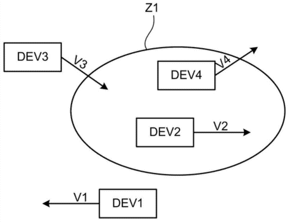
The invention relates to a method and system for communication between a first device party (DEV) and one or more other destination device parties (DEVs) implemented over a communication network (30), each device party based on its The geographic coordinates of are identified on said communication network (30) by means of an identifier (ID). The method comprises the step of dispatching a message via the first device party to each destination device party, said message being in accordance with a determined communication protocol and comprising determining for each destination device party whether said message is relevant thereto. A first item of information (AREA) defining an area of ​​influence (Z1) corresponding to the defined geographical area.

Description

technical field [0001] The present invention relates to methods and systems for communicating between a first device and one or more other devices. The invention also relates to devices employed in the communication system. Background technique [0002] For certain applications, such as eg the control of light, it is becoming increasingly common to use wireless technologies. The light can be controlled via a wireless link by means of a transmitter which communicates with a receiver which is equipped with an output for outputting a switch-on signal to the light. In order to communicate, the transmitter must be known to the receiver. Therefore, the method of coupling the transmitter and receiver must be implemented prior to normal use of the transmitter / receiver assembly. If a given transmitter is associated with a large number of receivers, for example to control a large number of lights, each receiver must be coupled to the transmitter. Existing solutions are less than s...

Claims


Application Information

Patent Timeline
Patent Type & Authority Patents(China)
IPC IPC(8): H04L12/28H04L29/12H04L29/08H04W8/00
CPCH04L12/281H04W8/005H04L61/50H04L2101/60H04L2101/69H04L67/51H04L67/52H04W64/003
Inventor R.加申T.西什
Owner SCHNEIDER ELECTRIC IND SAS
Learn More