Lifting mechanism of steel bar truss bending component

A technology of steel bar truss and lifting mechanism, applied in the field of steel bar trusses, can solve the problems of inability to adjust assembly and debugging requirements, and achieve the effect of simple structure and accurate height adjustment

Inactive Publication Date: 2013-11-27
WUXI WEIHUA ELECTRIC WELDING MFG
View PDF13 Cites 3 Cited by
  • Summary
  • Abstract
  • Description
  • Claims
  • Application Information

AI Technical Summary

Problems solved by technology

Most of the truss workpieces need to knuckle the lower part of the web reinforcement. The knuckle is realized by the knuckle assembly on the truss production line. The whole knuckle assembly is fixed, and the relative position of the knuckle body and the supporting part of the knuckle assembly is also fixed. Debug requirements cannot be adjusted

Method used


Image

  • Lifting mechanism of steel bar truss bending component
  • Lifting mechanism of steel bar truss bending component
  • Lifting mechanism of steel bar truss bending component

Examples


Embodiment Construction

[0015] Below the present invention will be further described in conjunction with the embodiment in the accompanying drawing:

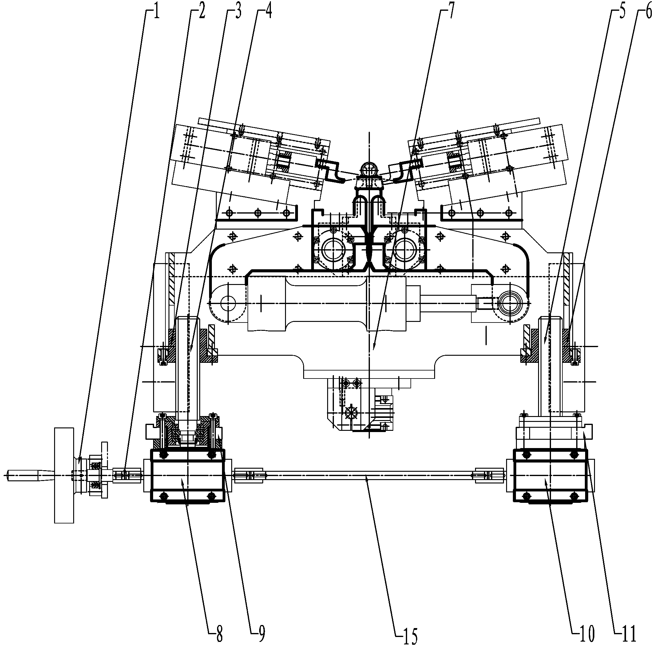
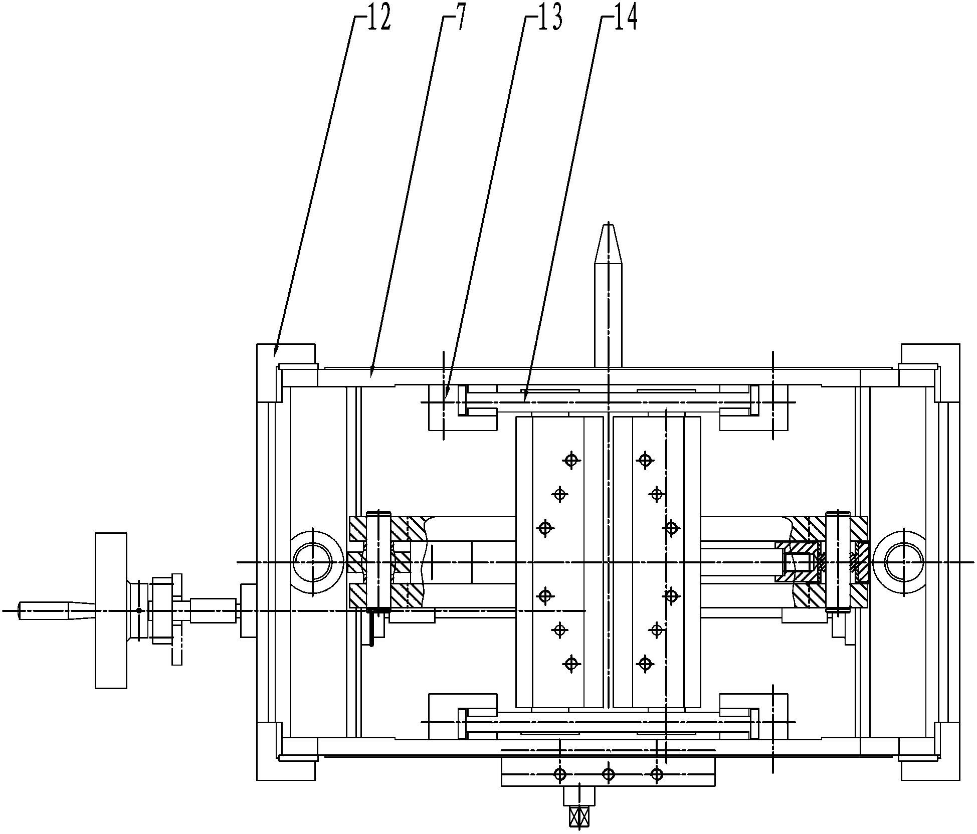
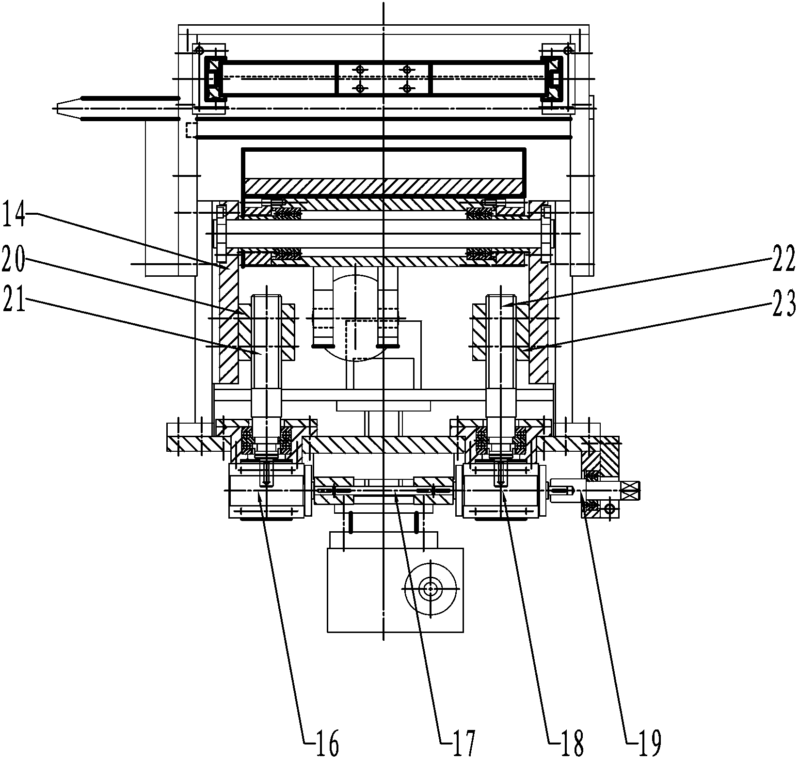
[0016] Such as Figure 1~3 As shown, the present invention mainly includes a first external speed reducer 8 and a second external speed reducer 10 , and the first external speed reducer 8 and the second external speed reducer 10 are connected through an external linkage connecting rod 15 . One end of the first external reducer 8 is connected to the handwheel 1 through the handwheel rotating shaft 2 .

[0017] The upper end of the first external reducer 8 is connected with the first outer screw rod 4 , and the first outer screw rod 4 is connected with the first outer screw rod sleeve 3 . The upper end of the second external reducer 10 is connected with the second outer screw rod 5 , and the second outer screw rod 5 is connected with the second outer screw rod sleeve 6 . The upper ends of the first outer screw sleeve 3 and the second outer screw sleeve...


PUM


Abstract

The invention relates to a lifting mechanism of a steel bar truss bending component, which is specifically used for adjusting relative positions of a break angle body and a fixed body, and belongs to the technical field of steel bar trusses. The lifting mechanism comprises a first outer speed reducer and a second outer speed reducer; the first outer speed reducer and the second outer speed reducer are connected through an outer linkage connecting rod; the upper end of the first outer speed reducer is connected to a first outer screw rod; the first outer screw rod is connected to a first outer screw rod sleeve; the upper end of the second outer speed reducer is connected to a second outer screw rod; the second outer screw rod is connected to a second outer screw rod sleeve; the upper ends of both the first outer screw rod sleeve and the second outer screw rod sleeve are connected to a break angle frame; the break angle frame is connected into an outer sliding support frame in a sliding manner; inner sliding support frames are fixed at two sides of the break angle frame. The lifting mechanism of the steel bar truss bending component has a simple, compact and reasonable structure, and can adjust relative positions of the break angle body and the fixed body as well as the height of the break angle frame; the height adjustment is precise.

Description

technical field [0001] The invention relates to a lifting mechanism for a bending part of a steel bar truss, in particular for adjusting the relative positions of an angled body and a fixed body, and belongs to the technical field of steel bar trusses. Background technique [0002] The steel truss mainly consists of one upper chord reinforcement (straight reinforcement), two lower chord reinforcements (straight reinforcement), and two web reinforcements (wavy). The upper chord reinforcement and the web reinforcement, the lower chord reinforcement and the web reinforcement are integrated by resistance welding. Most of the truss workpieces need to knuckle the lower part of the web reinforcement, and the knuckle is realized by the knuckle assembly on the truss production line. Debug requirements cannot be adjusted. Contents of the invention [0003] The purpose of the present invention is to overcome the above disadvantages, thereby providing a lifting mechanism for the ben...

Claims


Application Information

Patent Timeline
IPC IPC(8): B21F1/00
Inventor 袁彬彬
Owner WUXI WEIHUA ELECTRIC WELDING MFG
Why Eureka
Try Eureka