Tightening device, tightening binding tie assembly and packing box

A fastening device and cable tie technology, applied in the directions of packaging, transportation and packaging, flexible elongated elements, etc., can solve the problems of inability to reuse, damage, time-consuming and laborious packaging and unpacking, etc.

Inactive Publication Date: 2015-04-29
QISDA SUZHOU +1
View PDF6 Cites 0 Cited by
  • Summary
  • Abstract
  • Description
  • Claims
  • Application Information

AI Technical Summary

Problems solved by technology

[0003] In the process of unpacking, since the above-mentioned packaging materials in the prior art are all designed for one-time use, they will inevitably be damaged during the dismantling process, so they cannot be reused
In addition, when using the above-mentioned packaging materials to pack the product, professional tools are needed to complete it; also when unpacking, in order to remove the cable tie 12, the scotch tape must be torn off first, and then the cable harness should be cut with a tool similar to scissors Belt 12, so the packaging method using the above packaging materials is time-consuming and laborious when packing and unpacking

Method used


Image

  • Tightening device, tightening binding tie assembly and packing box
  • Tightening device, tightening binding tie assembly and packing box
  • Tightening device, tightening binding tie assembly and packing box

Examples


Embodiment 1

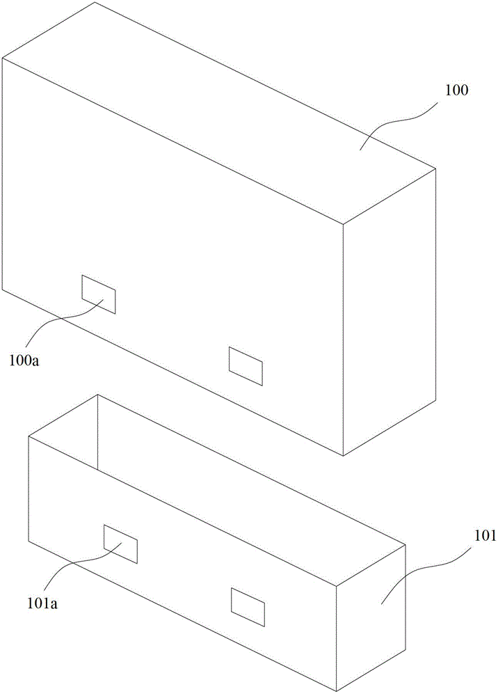
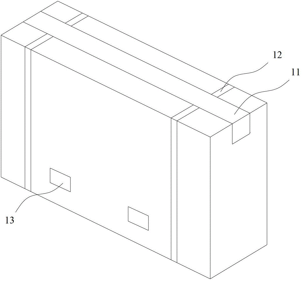
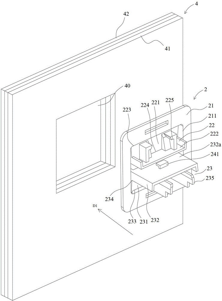
[0048] figure 2 A schematic diagram showing that the fastening device provided in this embodiment is in an open state, image 3 for figure 2 A schematic diagram of another perspective of the fastening device in , Figure 4 for figure 2 Schematic rear view of the fastening mechanism in ; see also Figure 2 to Figure 4 , figure 2 At the same time, it shows a plurality of sheets 4 to be clamped from the first direction D1. It should be noted that, in practice, the body to which the above-mentioned sheets 4 belong can be any kind of sheet with multiple layers in a certain area and needs to The clamped object is therefore in figure 2 The plate 4 shown in can be only a part of the main body having the plate 4, and the number of multiple plates 4 is not limited to figure 2 The 3 layers shown in , may also be 2 layers or any number greater than 3 layers.

[0049] exist figure 2 Among them, a plurality of sheets to be clamped form buttonholes 40 penetrating along the fir...

Embodiment 2

[0072] In the fastening device 2 in the above embodiment, the cable tie hook 241 is only formed on the locking seat 23 of the fastening device 2. In practice, the cable tie can also be formed only on the hook seat 22 of the fastening device 2. With a hook, now the two ends of the cable tie can be hooked on the cable tie hook on the hook seat 22, when the fastening device is switched from the open state to the fastened state, the cable tie can also be hooked tension. In addition, a cable tie hook can also be provided on the hook seat 22 and the locking seat 23 of the fastening device respectively, Figure 15 to Figure 19 A structural schematic diagram of a fastening device with a cable tie hook provided on each of the hook seat and the locking seat is shown. Figure 15 to Figure 19 Winning mark and Figure 2 to Figure 12 Structures with the same number refer to the same components, which will not be repeated here.

[0073] Figure 15 A schematic diagram showing that the fas...

Embodiment 3

[0079] In practice, the cable ties all have a certain thickness, especially considering the requirement of binding strength, the thickness of the cable tie cannot be ignored in the design process of the fastening device. In the first and second embodiments, the When the fastening device 2, 2' is in the fastened state, there is a certain gap between the hook seat 22 and the locking seat 23 of the fastening device 2, 2', and the gap is used to leave a space for the cable tie , but this implementation also has a gap in addition to the position of the cable tie, so to a certain extent, it affects the sealing performance of the fastening device 2, 2' in the fastened state. The fastening device in this embodiment is in the A further improvement is made here. When the hook seat 22 and the locking seat 23 swing to the position of the buckled state, at least one of the first base wall 221 and the second base wall 231 is opposite to each other. A gap is formed. In the following, the ab...


PUM


Abstract

The invention provides a tightening device, a tightening binding tie assembly and a packing box. The tightening device comprises an annular fixing plate which abuts against the position around a buckling hole in a first panel, facing the direction reverse to the first direction, from a plurality of panels to be clamped in an erected mode. The tightening device further comprises a clamping hook base and a clamping stopping base which are connected with the two opposite side edges of a central through hole of the annular fixing plate in a swinging mode respectively. When swinging towards the first direction to the position of the buckling state, the clamping hook base and the clamping stopping base abut against a second panel, facing the first direction, from the panels to be clamped in an attached mode. When the clamping hook base and / or the clamping stopping base swing / swings to the position of the buckling state, the faces / the face, facing the first direction, of the clamping hook base and / or the clamping stopping base are / is provided a binding tie clamping hook / binding tie clamping hooks for hooking the end portion of a binding tie. According to the embodiment, packing and unpacking are convenient, and packing materials can be repeatedly used after unpacking.

Description

technical field [0001] The invention relates to the technical field of packaging boxes, in particular to a fastening device, a fastening cable tie assembly and a packaging box packed with the fastening cable tie assembly. Background technique [0002] Traditional product packaging methods include one-piece A-shaped box packaging and upper and lower two-piece C-shaped box packaging, where the top edge of the A-shaped box has multiple sheets that can be folded towards the center, while the C-shaped box consists of The case base and the case cover outside the case base form. Figure 1A A schematic diagram of the exploded structure of the upper and lower two-piece C-shaped box is shown in , as Figure 1A As shown, the C-shaped box is composed of a box cover 100 and a box seat 101. During the use of the C-shaped box, the box cover 100 is covered outside the box seat 101. At this time, there is a part between the box cover 100 and the box seat 101. In the overlapping area, when pa...

Claims


Application Information

Patent Timeline
Patent Type & Authority Patents(China)
IPC IPC(8): B65D63/00B65D55/02
Inventor 李志文
Owner QISDA SUZHOU
Why Eureka
Try Eureka