Thermal injection pipe column and thermal injection valve of heavy oil thermal recovery well

A technology of heavy oil thermal recovery and heat injection valve, which is applied in the direction of wellbore/well valve device, production fluid, earthwork drilling and production, etc. It can solve the problems of insensitivity, inconvenient replacement, large adjustment parts, etc., and achieve flow control Sensitive, simple structure, avoiding damage

Active Publication Date: 2013-11-27
CHINA NAT OFFSHORE OIL CORP +1
View PDF4 Cites 7 Cited by
  • Summary
  • Abstract
  • Description
  • Claims
  • Application Information

AI Technical Summary

Problems solved by technology

In addition, although some gas injection devices can be adjusted according to changes in formation pressure, the adjustment parts are large and insensitive, and cannot be easily replaced

Method used


Image

  • Thermal injection pipe column and thermal injection valve of heavy oil thermal recovery well
  • Thermal injection pipe column and thermal injection valve of heavy oil thermal recovery well
  • Thermal injection pipe column and thermal injection valve of heavy oil thermal recovery well

Examples


Embodiment Construction

[0026] Embodiments of the present invention will be described in detail below in conjunction with the accompanying drawings. It should be noted that, in the case of no conflict, the embodiments in the present application and the features in the embodiments can be combined arbitrarily with each other.

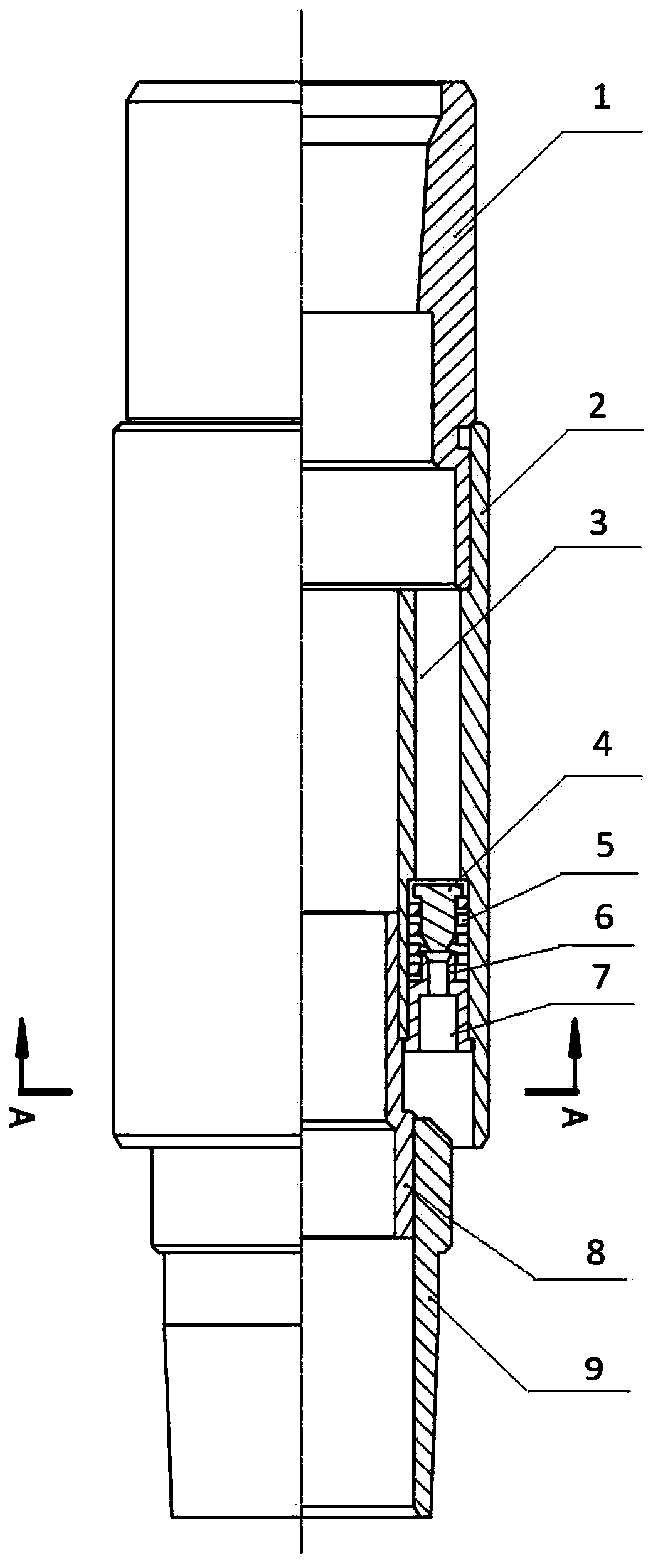
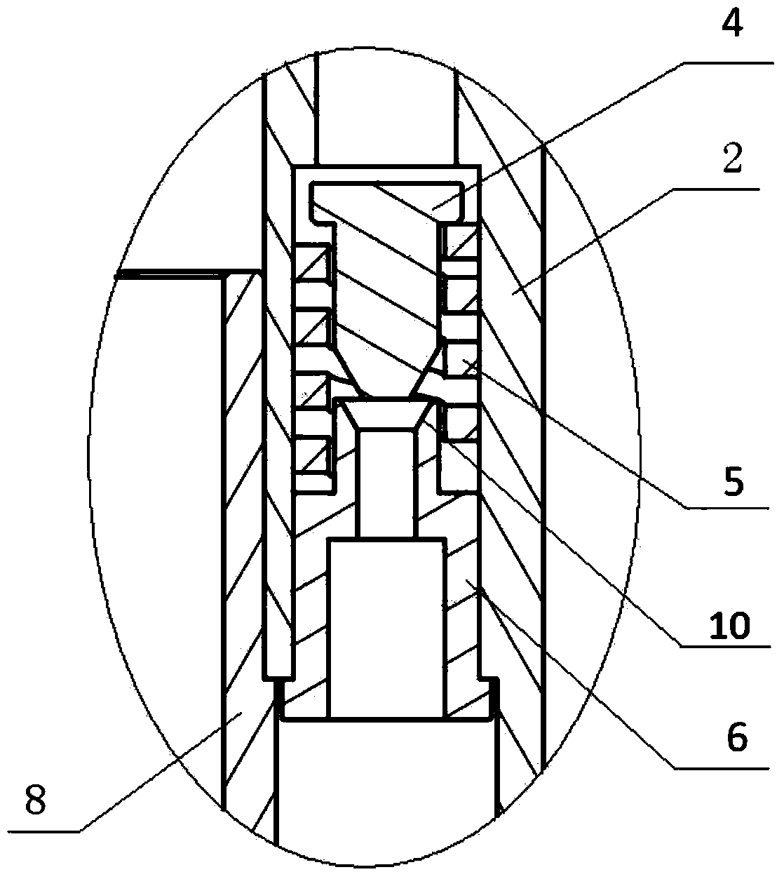
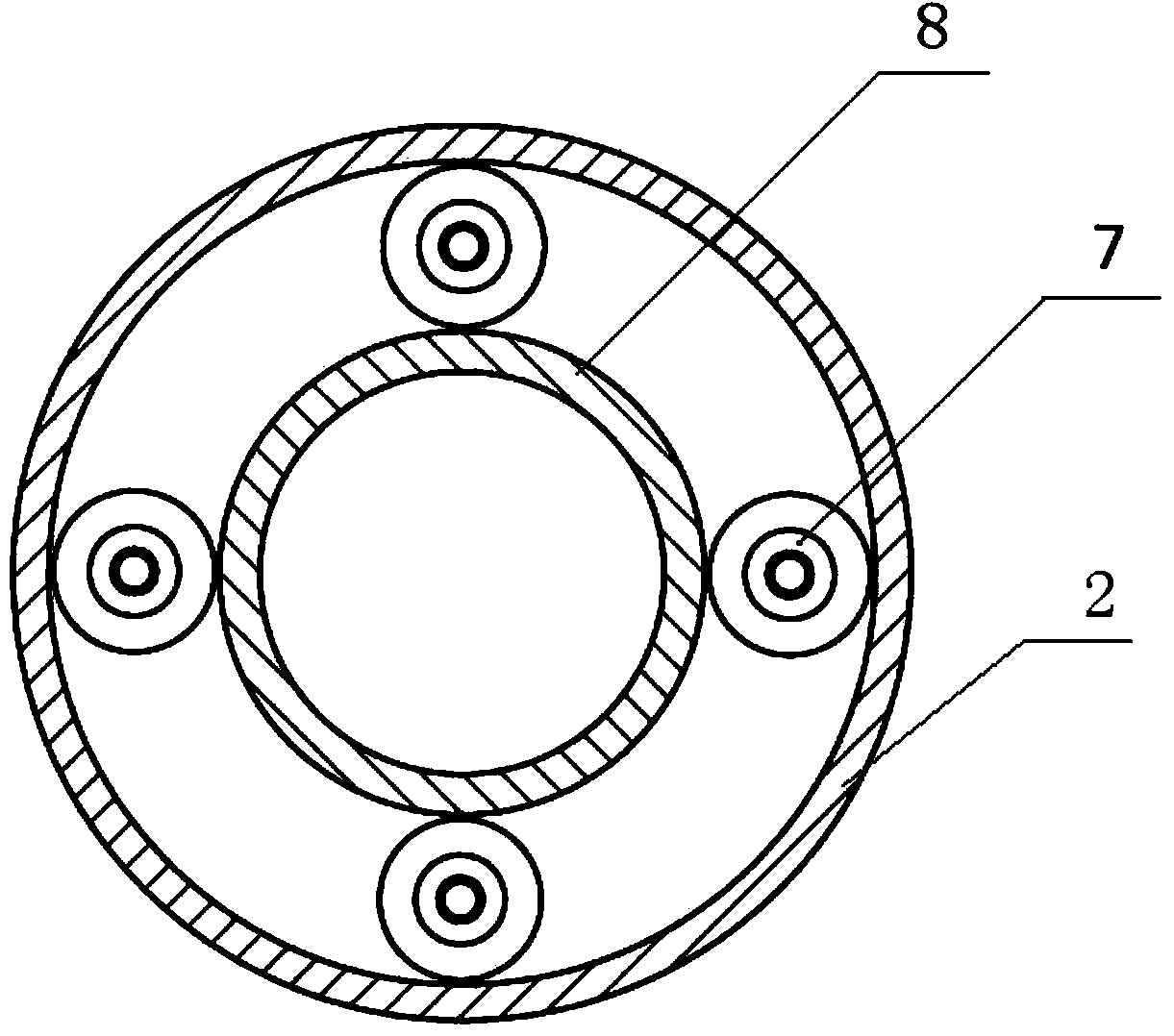
[0027] figure 1 It is a structural schematic diagram of the self-adjusting heat injection valve of the heavy oil thermal recovery well of the present invention; figure 2 for figure 1 A partial enlargement of the . image 3 yes figure 1 A-A sectional view;

[0028] The heat injection valve of the heavy oil thermal recovery well of the embodiment of the present invention is realized in this way, see figure 1 As shown, it includes an upper joint 1, a guide tube 2, a central pipe 8 and a lower joint 9 which are threaded sequentially from top to bottom. The threads are connected, the inner thread at the lower end of the guide tube 2 is connected with the outer thread at the up...


PUM


Abstract

The invention provides a thermal injection valve of a heavy oil thermal recovery well. The thermal injection valve comprises an upper joint, a guide cylinder, a center pipe and a lower joint which are sequentially connected from top to bottom; the cylinder wall of the guide cylinder is provided with a plurality of flow dividing hole channels which are communicated from top to bottom; the axis of the flow dividing hole channels is parallel to the axis of the guide cylinder; a flow regulating ring, a springback body and a valve core are arranged in the flow dividing hole channels; the flow regulating ring is fixed at the lower end in the flow dividing hole channels; the valve core is located above the flow regulating ring; the outer circular conical surface which is arranged at the lower end of the valve core is matched with the inner circular conical surface which is arranged at the upper end of the flow regulating ring; the flow regulating ring is provided with a flow channel from the inner circular conical surface of the flow regulating ring to the lower end of the flow regulating ring; the springback body is located between the valve core and the flow regulating ring. The thermal injection valve of the heavy oil thermal recovery well has the advantages of enabling the flow of injected fluid to be automatically regulated and being uniform in gas injection, simple in structure, free of large moving parts, sensitive in flow control and convenient to replace.

Description

technical field [0001] The invention relates to a downhole tool for thermal recovery of heavy oil, in particular to a heat injection pipe string and a heat injection valve of a thermal recovery well for injecting high-temperature fluid in a thermal recovery well for heavy oil. Background technique [0002] my country's Bohai Oilfield is rich in heavy oil reserves, but Bohai heavy oil is mostly exploited by cold recovery, and its output is very limited. In recent years, with the continuous development of some thermal recovery technologies such as offshore multi-component thermal fluid, more and more offshore heavy oil fields are being exploited by thermal recovery. On the other hand, with the continuous development of horizontal well technology, horizontal wells are widely used in the field of heavy oil production due to their large oil drainage area and high degree of reservoir production. In the horizontal well, due to the relatively long horizontal section, the pressure c...

Claims


Application Information

Patent Timeline
Patent Type & Authority Applications(China)
IPC IPC(8): E21B34/02E21B43/24
Inventor 孙永涛王通刘花军顾启林马增华张卫行刘海涛王少华
Owner CHINA NAT OFFSHORE OIL CORP
Why Eureka
Try Eureka