Wind indicator

A technology of wind vane and wind vane, applied in the field of wind vane, can solve the problems of clogging of the rotating head, bearing wear, easy freezing of the wind vane and the rotating cover, etc., so as to avoid the blockage of wind and sand.

Inactive Publication Date: 2013-11-27
曹二林 +1
View PDF4 Cites 7 Cited by
  • Summary
  • Abstract
  • Description
  • Claims
  • Application Information

AI Technical Summary

Problems solved by technology

[0003] The purpose of the invention is to solve the problems that the wind vane and the rotating cover of the w

Method used


Image

  • Wind indicator
  • Wind indicator
  • Wind indicator

Examples


Embodiment Construction

[0014] Below in conjunction with accompanying drawing and specific embodiment, further illustrate the present invention, it should be understood that these embodiments are only used to illustrate the present invention and are not intended to limit the scope of the present invention, after having read the present invention, those skilled in the art understand various aspects of the present invention Modifications in equivalent forms all fall within the scope defined by the appended claims of this application.

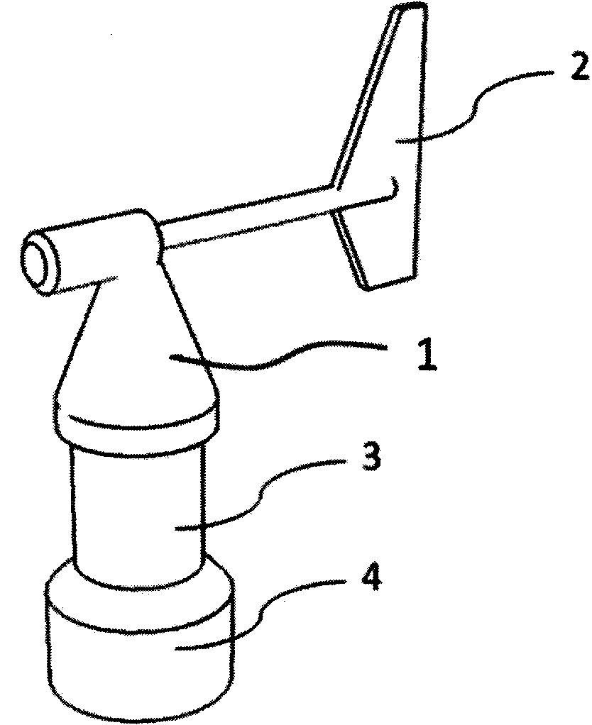
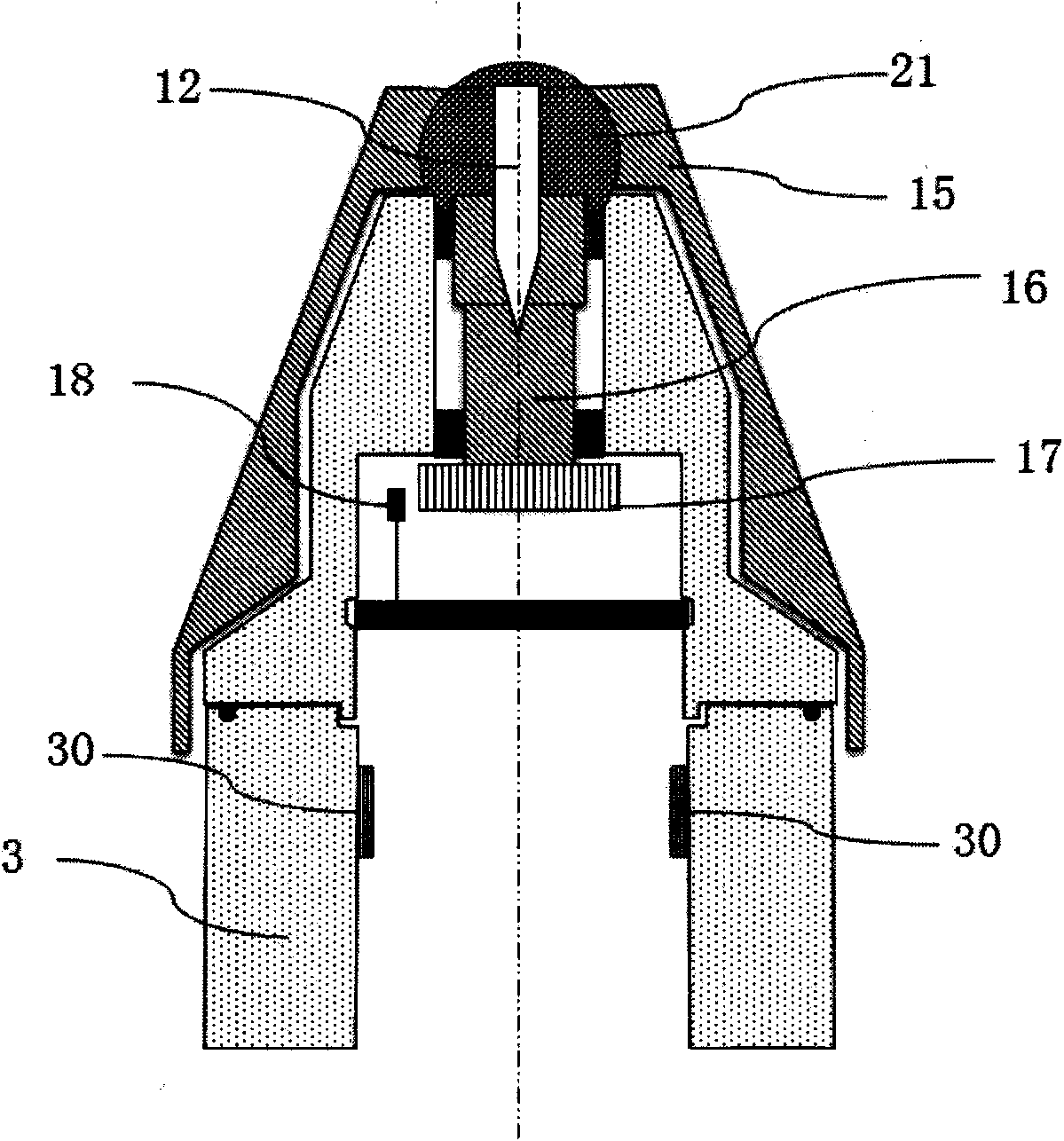
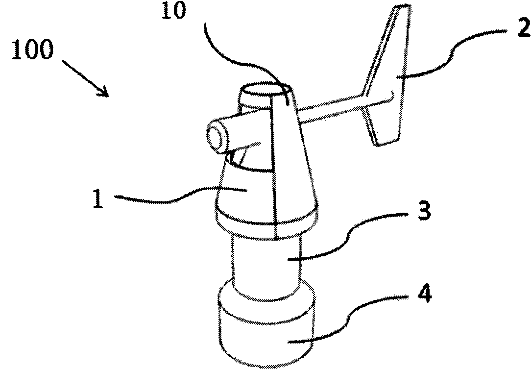
[0015] The present invention is improved on the basis of the structure of the existing anemometer, and the difference from the prior art is that the protective cover of the rotating head is added, and the heat conduction wire is placed on the protective cover. like image 3 Shown is a perspective view of the wind vane of the present invention, and the wind vane 100 includes: a wind vane 2 , a rotating head 1 driven by the wind vane to rotate, a supporting body 3 and a ba...


PUM


Abstract

The invention discloses a wind indicator, and relates to a wind power generation wind indicator. The wind indicator comprises a wind vane and a rotating head driven by the wind vane to rotate; a protective cover is arranged on the rotating head, and is perpendicular to the wind vane; a heating device is arranged on the protective cover, and adopts a heater strip. Through the technical scheme that the heating device is arranged on the protective cover, the protective cover is taken as a guidance to quickly transmit heat to the wind vane and a rotating cover of the wind indicator, the problem that as the rotating cover and the wind vane of the wind indicator are easily frozen under the low temperature freezing environment, the wind indicator does not work is solved effectively. Meanwhile, the protective cover prevents sand, so that the rotating head is prevented from being blocked by sand.

Description

technical field [0001] The invention relates to an anemometer, in particular to an anemometer for wind power generation. Background technique [0002] figure 1 It is a traditional wind vane, which consists of a wind vane 2 , a rotating head 1 , a branch 3 and a base 4 . The wind makes the wind vane 2 point to the direction of the wind source, and drives the bearing 16 of the rotating head 1 so that the position of the code disc 17 connected to the bearing 16 changes. And calculate the position that code disc moves by degree device 18, judge the concrete direction of wind, as figure 2 The sectional view shown. Simultaneously, increase and add the heating wire 30 with high power on branch body 3, avoid because under the environment of cryogenic freezing, easily take place freezing on the rotating cover 15 of anemometer and wind vane 2, cause not working. However, due to the existence of bearings and other structures inside the wind vane, the heat of the heating wire is di...

Claims


Application Information

Patent Timeline
IPC IPC(8): F03D11/00G01P13/02
CPCY02E10/722
Inventor 曹二林其他发明人请求不公开姓名
Owner 曹二林
Why Eureka
Try Eureka