Eureka AIR delivers breakthrough ideas for toughest innovation challenges, trusted by R&D personnel around the world.

Swirl Pulverized Coal Burner Inner Shrinking Outer Expansion Nozzle

A pulverized coal burner and retractable technology, which is applied to burners, burners for burning powder fuel, combustion methods, etc., can solve the problem of reducing the ignition and stable combustion performance of the pulverized coal gas flow of the nozzle, impairing the ignition and stable combustion performance of pulverized coal, Boiler safety operation requirements hidden dangers and other issues, to achieve good application prospects, strengthen ignition and stable combustion performance, and avoid the effect of pulverized coal concentration dilution

Active Publication Date: 2016-05-25
中节环立为(武汉)能源技术有限公司
View PDF5 Cites 0 Cited by
  • Summary
  • Abstract
  • Description
  • Claims
  • Application Information

AI Technical Summary

Problems solved by technology

Since the combustion stabilizing teeth or the combustion stabilizing ring are installed inside the nozzle of the pulverized coal burner, although the turbulence intensity to the boundary of the pulverized coal flow is enhanced, it is insufficient for the enhanced heat exchange with the external hot flue gas, so the combustion stabilization effect poor
At the same time, the study found that during the ignition process of the pulverized coal flow, if the external secondary air jet enters the pulverized coal jet prematurely, it will lead to a decrease in the concentration of the pulverized coal and an increase in the heat required for the pulverized coal to ignite, which will greatly damage the pulverized coal ignition. Flame stability
Moreover, it was found during use that the combustion stabilizing teeth or the stabilizing combustion ring in the pulverized coal airflow were directly impacted by the pulverized coal particles. The wear-through phenomenon reduces the ignition stability of the pulverized coal flow ejected from the nozzle, which brings great hidden dangers to the safe operation requirements of the boiler.

Method used


Image

  • Swirl Pulverized Coal Burner Inner Shrinking Outer Expansion Nozzle
  • Swirl Pulverized Coal Burner Inner Shrinking Outer Expansion Nozzle
  • Swirl Pulverized Coal Burner Inner Shrinking Outer Expansion Nozzle

Examples


Embodiment 1

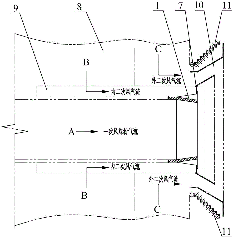
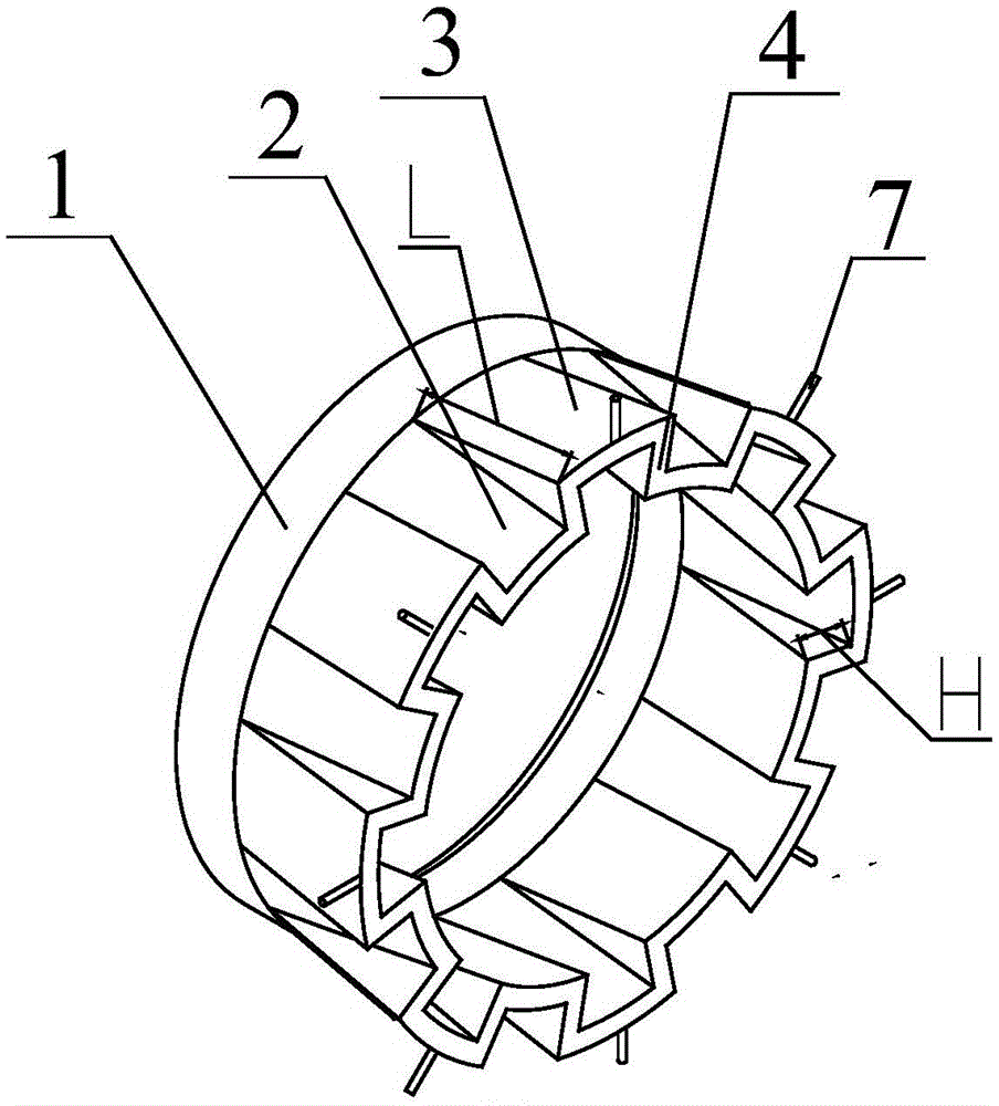
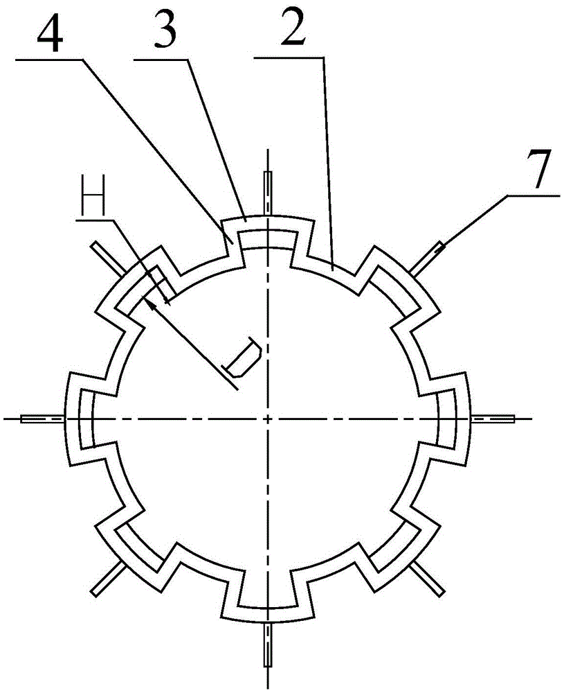
[0029] Such as Figure 2~3 A swirl pulverized coal burner shown in the figure has a shrinking and expanding nozzle, which has a nozzle body 1. The nozzle section of the nozzle body 1 has a double-sided battlement diversion structure, and it includes retractable guide vanes 2 arranged staggered along the circumferential direction. And the outwardly expanding guide vane 3, the retractable guide vane 2 is based on the inner diameter D of the nozzle section of the nozzle body 1, and the section radius from the root to the end is gradually reduced, and the outwardly expanding guide vane 3 is based on the nozzle The inner cavity diameter D of the nozzle section of the body 1 is based on the cross-sectional radius from the root to the end gradually increases, and the radial transition plate of the triangular structure is passed between the adjacent retractable guide vanes 2 and the outwardly expanded guide vanes 3 4 in one.

[0030] When optimizing the design, the inner cavity diame...

Embodiment 2

[0034] Such as Figure 4~5Another kind of swirl pulverized coal burner shown is the shrinking and expanding nozzle, its overall structure is basically the same as that of Embodiment 1, except that the outer side of the end of the shrinking deflector 2 is welded with a shrinking end stable combustion block The sheet 5 and the internally retracted end combustion stabilizing baffle 5 are arranged perpendicular to the axis line of the nozzle section of the nozzle body 1 . When optimizing the design, the radial height h1 of the combustion-stabilizing baffle 5 at the retracted end and the radial height H from the inner wall of the retracted guide vane 2 to the inner wall of the expanded guide vane 3 satisfy the following mathematical relationship: h1= 0.5~1.0H. In this embodiment, h1=0.8H. The internally retracted end combustion stabilizing baffle 5 can effectively prevent the internal secondary air flow B from entering the primary air pulverized coal flow A prematurely, thereby a...

Embodiment 3

[0036] Such as Figure 6~7 The third kind of swirl pulverized coal burner shown is the shrinking and expanding nozzle. Its overall structure is basically the same as that of Embodiment 1, except that the outside of the end of the expanding deflector 3 is welded with an expanding end stable combustion block. The sheet 6 and the flame-stabilizing baffle at the outer expansion end are arranged perpendicular to the axis line of the nozzle section of the nozzle body 1 . When optimizing the design, the radial height h2 of the combustion-stabilizing baffle 6 at the outer expansion end and the radial height H from the inner wall of the retractable guide vane 2 to the inner wall of the outward expansion guide vane 3 satisfy the following mathematical relationship: h2= 0.5~2.0H. In this embodiment, h2=0.9H. The externally expanded end combustion stabilization baffle 6 can effectively prevent the internal secondary air flow B from entering the primary air pulverized coal flow A prematu...


PUM


Abstract

The invention discloses an internal contraction and external expansion type nozzle for a swirl pulverized coal burner. The opening section of a nozzle body is in a two-sided battlement guide structure and comprises internal contraction type flow deflectors and external expansion type flow deflectors which are arranged circumferentially in a staggered mode, radiuses of sections of the internal contraction type flow deflectors from the root to the end decrease gradually with the diameter D of the inner cavity of the opening section of the nozzle body serving as the reference, radiuses of sections of the external expansion type flow deflectors from the root to the end increase gradually with the diameter D of the inner cavity of the opening section of the nozzle body serving as the reference, and adjacent internal contraction type flow deflectors and external expansion type flow deflectors are connected through radial transition plates. The internal contraction and external expansion type nozzle has a good guide effect on pulverized coal airflow, direct impact of pulverized coal particles on the nozzle is reduced, the pulverized coal airflow is mixed with external hot smoke intensely for heat exchange when sprayed from the nozzle, strong ignition and stable combustion performances of the pulverized coal are guaranteed, the pulverized coal airflow resistance can be effectively reduced, abrasion to the nozzle is small, and the service life of the nozzle is long. The internal contraction and external expansion type nozzle is particularly suitable for coal-fired boilers of swirl pulverized coal burners with front and back walls in cross arrangement.

Description

technical field [0001] The invention relates to a pulverized coal burner in a coal-fired boiler, in particular to an inwardly contracting and outwardly expanding nozzle of a swirl pulverized coal burner. Background technique [0002] In large coal-fired boilers of 600MW and above, most of them adopt the structure of the front and rear walls of the swirling pulverized coal burner, but the swirling pulverized coal burner was only suitable for burning bituminous coal and sub-bituminous coal with high volatile content in the past. With the change of coal quality for domestic power plant boilers, more and more low-volatile coals have gradually become the main coal for boilers. In response to this situation, the development of a swirling pulverized coal burner suitable for burning low-volatile lean coal and anthracite has very broad market and technical prospects. Especially in order to meet the low-load operation requirements of large boilers and in the case of poor coal quality...

Claims


Application Information

Patent Timeline
Patent Type & Authority Patents(China)
IPC IPC(8): F23D1/02
Inventor 张泽曹明侠熊巍
Owner 中节环立为(武汉)能源技术有限公司
Why Eureka
Eureka Blog
Learn More