Multi-directional jet swirl pulverized coal burner

A pulverized coal burner and jet type technology, which is applied to burners, burners burning powder fuels, and burning with various fuels, etc., can solve the hidden dangers of safe and stable operation of boilers, hidden dangers of high temperature corrosion of water walls, and lack of oxygen in pulverized coal. Combustion and other problems, to avoid high-temperature corrosion and scouring of pulverized coal gas flow, to eliminate high-temperature corrosion and coking hidden dangers, and to strengthen the performance of ignition and stable combustion

Active Publication Date: 2016-01-27
中节环立为(武汉)能源技术有限公司
View PDF6 Cites 0 Cited by
  • Summary
  • Abstract
  • Description
  • Claims
  • Application Information

AI Technical Summary

Problems solved by technology

In order to meet the environmental protection boiler low-nitrogen combustion requirements of power plants, oxygen-deficient and low-nitrogen combustion air distribution is implemented in the boiler pulverized coal combustion, which is more likely to cause the pulverized coal to burn anoxic near the water wall, forming a high-temperature and reducing atmosphere, and bringing water to the water wall. Serious hidden danger of high temperature corrosion
Especially in the operation process of the boiler with the front and rear walls opposed to each other, due to the swirling flow of the external secondary air jet and the negative pressure zone between the burner and the water wall, the surrounding high-temperature hot flue gas is driven back to supplement, resulting in Coal powder is prone to stick to the wall near the water wall of the furnace, and it is more likely to cause severe high-temperature corrosion and coking on the water wall of the furnace under anoxic conditions. The occurrence of such situations will bring great hidden dangers to the safe and stable operation of the boiler. At the same time, a large amount of maintenance costs are generated every year
In particular, Zhundong coal, which contains a large amount of sodium, potassium and alkali metals, has been widely used in recent years, and it is more likely to cause severe high-temperature corrosion and coking of the furnace water wall when the boiler is fired.

Method used


Image

  • Multi-directional jet swirl pulverized coal burner
  • Multi-directional jet swirl pulverized coal burner
  • Multi-directional jet swirl pulverized coal burner

Examples


Embodiment 1

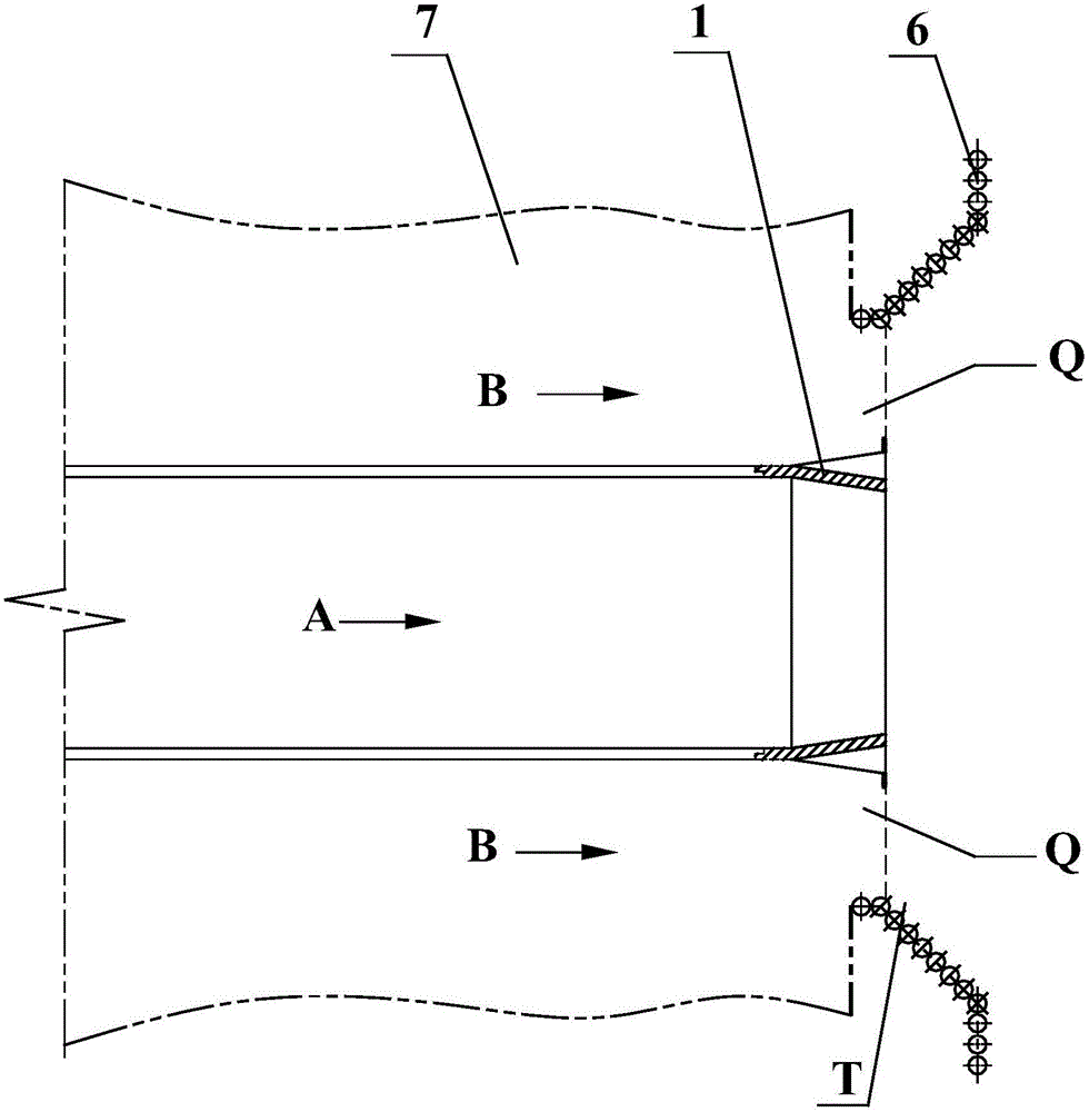
[0035] Such as figure 2 As shown, a multi-directional jet type swirl pulverized coal burner of the present invention is installed in the air box 7 outside the coal-fired boiler, and is connected with the opening on the furnace water wall 6. The primary air pulverized coal nozzle 1, an annular secondary air flow nozzle Q is formed between the outer periphery of the primary air pulverized coal nozzle 1 and the opening on the furnace water wall 6, and a wall-adhering wind guide tube 3 is arranged inside the secondary air flow nozzle Q , an annular wall-adhering air jet nozzle T is formed between the wall-adhering wind guide tube 3 and the opening on the furnace water wall 6, and the flow area of ​​the outlet of the wall-adhering air jet nozzle T accounts for 3% of the outlet flow area of ​​the secondary air flow nozzle Q ~18%; when optimizing the design, the flow area of ​​the wall-adhering air jet nozzle T outlet accounts for 3~12% of the flow area of ​​the secondary air flow n...

Embodiment 2

[0043] Such as Figure 10 As shown, another multi-directional jet swirl pulverized coal burner of the present invention has the same overall structure as that of Embodiment 1, except that the flanging air guide flange 5 is arranged at a position flush with the furnace water wall 6 , so that the wall-adjacent wind can be injected into the furnace at an angle relative to the water wall 6 of the furnace.

Embodiment 3

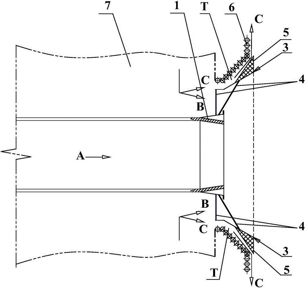
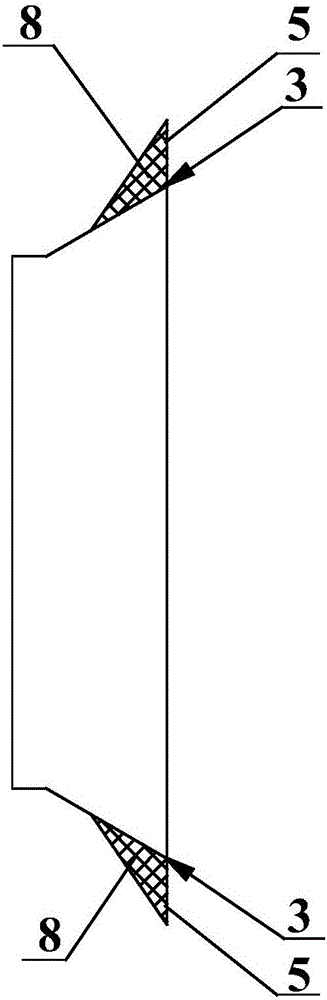
[0045] Such as Figure 11 As shown, the third multi-directional jet type swirl pulverized coal burner of the present invention has the same overall structure as that of Embodiment 1, except that the outer periphery of the primary air pulverized coal nozzle 1 is provided with a secondary air guide tube 2, attached to The wall wind guide tube 3 is arranged between the secondary air guide tube 2 and the spout on the furnace water wall 6 , and is rigidly connected to the outer wall of the secondary air guide tube 2 through the supporting device 4 .

[0046] When it works, coal powder and primary air form a primary air pulverized coal airflow A, which is sprayed into the furnace by the primary air pulverized coal nozzle 1; The wind flow B is blown into the furnace from the inside and outside of the wall of the secondary wind guide tube 2 in two ways, and is mixed with the primary air pulverized coal flow A to fully burn the pulverized coal and play a combustion-supporting role. Th...


PUM


Abstract

The invention discloses a multi-directional jet-type cyclone pulverized coal burner. The multi-directional jet-type cyclone pulverized coal burner is installed in a bellow on the outer side of a coal-fired boiler and connected with an opening in a combustion chamber water wall. The multi-directional jet-type cyclone pulverized coal burner comprises a primary air pulverized coal nozzle installed in a direction perpendicular to the combustion chamber water wall, the periphery of the primary air pulverized coal nozzle and the opening in the combustion chamber water wall form an annular secondary air flow nozzle, a wall-attached air guide cylinder is arranged in the secondary air flow nozzle, the wall-attached air guide cylinder and the opening in the combustion chamber water wall form an annular wall-attached air jet flow nozzle, and the circulation area of the outlet of the wall-attached air jet flow nozzle accounts for 3-18% of the circulation area of the secondary air flow nozzle. According to the multi-directional jet-type cyclone pulverized coal burner, on the premise that the structure of a conventional cyclone pulverized coal burner is not greatly changed, part of separated secondary air is enabled to form a mobile oxidation air film on the surface of the water wall through adding the wall-attached air guide cylinder, the surface of the water wall on the periphery of the burner is ensured to be in an oxidizing atmosphere, and high-temperature corrosion and coking to the combustion chamber water wall nearby the burner are avoided.

Description

technical field [0001] The invention relates to the technical field of a swirl pulverized coal burner, in particular to a multi-directional jet type swirl pulverized coal burner. Background technique [0002] At present, due to the wide application of low-nitrogen combustion technology in large thermal power boilers, the wall surface coking and high-temperature corrosion of the furnace water wall are becoming more and more serious, which has gradually become an important factor that threatens the safe and stable operation of power plant boilers. Changes in coal quality, pipe wall temperature, and flue gas composition changes near the water wall of the furnace are all factors that cause coking and high temperature corrosion on the water wall of the furnace. In order to meet the environmental protection boiler low-nitrogen combustion requirements of power plants, oxygen-deficient and low-nitrogen combustion air distribution is implemented in the boiler pulverized coal combusti...

Claims


Application Information

Patent Timeline
Patent Type & Authority Patents(China)
IPC IPC(8): F23D1/02F23C5/08
Inventor 张泽熊巍曹明侠
Owner 中节环立为(武汉)能源技术有限公司
Why Eureka
Try Eureka