Quick mold changing device, injection molding machine, and quick mold changing method for injection molding machine

An injection molding machine, fast technology, applied in the field of quick mold change, can solve the problem of reducing the time of fastening bolts, etc., and achieve the effect of improving the efficiency of mold change

Active Publication Date: 2016-07-06
GREE ELECTRIC APPLIANCES INC
View PDF6 Cites 2 Cited by
  • Summary
  • Abstract
  • Description
  • Claims
  • Application Information

AI Technical Summary

Problems solved by technology

[0004] The purpose of the present invention is to provide a mold clamping tool and a mold changing method to replace the clamping plate and bolts to fix the mold, reduce the time for the mold setter to fasten the bolts during the mold change process, and at the same time solve the problem that the clamping plate can only be judged by the experience of the mold loader. Whether the bolts are fastened and other safety hazards

Method used


Image

  • Quick mold changing device, injection molding machine, and quick mold changing method for injection molding machine
  • Quick mold changing device, injection molding machine, and quick mold changing method for injection molding machine

Examples


Embodiment 1

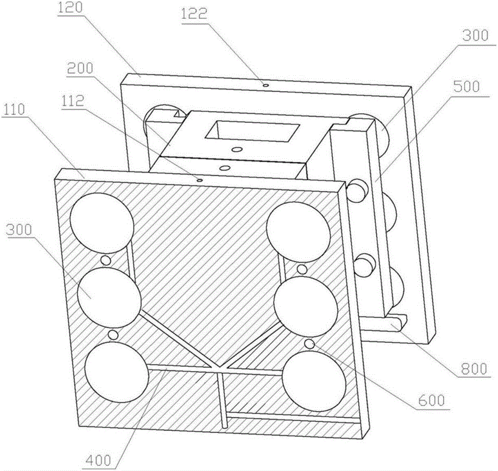
[0042] like figure 1 As shown, the mold loading tooling in this embodiment includes two mold backing plates for clamping the mould, which are respectively a front mold backing plate 110 and a rear mold backing plate 120, and the mold 200 is loaded on the two mold backing plates 110 , 120, the two mold backing plates 110, 120 are provided with a pneumatic device that can fix or unfix the mold 200 on the plate body.

[0043] Preferably, the pneumatic device includes a pneumatic chuck 300 and a chuck air passage 400 communicating with it for introducing gas, such as figure 2 Shown; Pneumatic chuck 300 is respectively placed on the plate body of mold backing plate 110,120;

[0044] Pneumatic chuck 300 is a standard part, which penetrates and is arranged on the plate body of formwork backing plate 110, 120, and its inner end surface is provided with a horizontal drag hook located between two formwork backing plates 110, 120; use standard pneumatic chuck 300 , easy to design and ...

Embodiment 2

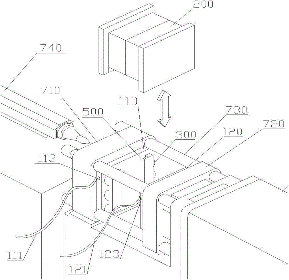
[0049] like figure 2 As shown, the injection molding machine in this embodiment includes a front size template 710 and a rear size template 720, and four guide positioning columns 730 are arranged between the front size template 710 and the rear size template 720; the injection molding machine also includes the first embodiment. The quick mold changing device and the high-pressure air pipes 111, 121 for inputting high-pressure gas;

[0050] The output ends of the high-pressure air pipes 111, 121 respectively penetrate into the plates of the two mold backing plates 110, 120 of the mold loading tooling, and communicate with the chuck air passage 400;

[0051] The two mold backing plates 110, 120 of the quick mold changing device are respectively fixed on the inner sides of the front and rear code templates 710, 720 of the injection molding machine.

[0052] Preferably, the two mold support plates 110, 120 of the quick mold change device are smaller than the front and rear code t...

Embodiment 3

[0057] The quick mold change method of the injection molding machine in this embodiment uses the injection molding machine in Embodiment 2; wherein, the injection molding machine also includes a mold ejector rod and a heating nozzle console 740;

[0058] The method includes the steps of dismantling old molds and loading new molds;

[0059] Wherein, the content of the operation of described loading new mold comprises:

[0060] Slowly open the front and rear mold plates 710 and 720 of the injection molding machine, adjust the position of the ejector rod of the injection molding machine to return, and withdraw the heating nozzle console 740 of the injection molding machine from the front mold plate 710, the push-out distance is 15 to 20 mm; the new mold is hoisted between the mold backing plates 110, 120 fixed on the inside of the front and rear code templates 710, 720; The joints 113 and 123 are connected, and the high-pressure gas is input to the pneumatic chuck 300 through th...


PUM


Abstract

The invention discloses a rapid mold changing device. The rapid mold changing device comprises a mold base plate for clamping molds, and a pneumatic device which can fix a mold or remove the fixation is arranged on the plate body of the mold base plate. The invention also discloses an injection machine using the rapid mold-changing device, and a use method of the injection machine. According to the rapid mold changing device, the injection machine and the use method of the injection machine, a rapid mold changing process is achieved by an automatic locking mode. In a prior mold changing mode, mold base plate mounting and dismounting time accounts for about 42% of the whole mold changing time. Through use of the injection machine and the rapid mold changing method thereof, the whole mold changing efficiency is improved by more than 40%.

Description

technical field [0001] The invention relates to a mold changing equipment, in particular to a quick mold changing device for an injection molding machine, an injection molding machine using the quick mold changing device and a quick mold changing method for the injection molding machine. Background technique [0002] Injection molding machine is the main equipment for manufacturing compression molding products. When working, it is necessary to assemble and replace the mold used for product molding; at present, the traditional bolt and platen type manpower is used to install and disassemble the mold on the injection molding machine. Operation, since this method is manually installed by the molder during the entire mold changing process, it is limited by the experience, physical strength, and labor time of the molder, and the efficiency of the mold loading process is low. The length of time is difficult to be effectively guaranteed. [0003] At present, the hydraulic mold cla...

Claims


Application Information

Patent Timeline
Patent Type & Authority Patents(China)
IPC IPC(8): B29C45/17B29C33/30
Inventor 刘星星
Owner GREE ELECTRIC APPLIANCES INC
Why Eureka
Try Eureka