Pipe end machine convenient for die changing

A tube end machine and rack technology, applied in the field of tube end machines, can solve the problems of low stamping efficiency, unfavorable enterprise development, time-consuming and labor-intensive, etc.

Pending Publication Date: 2020-07-07
广东弘毅智能装备有限公司
View PDF0 Cites 1 Cited by
  • Summary
  • Abstract
  • Description
  • Claims
  • Application Information

AI Technical Summary

Problems solved by technology

However, such a stamping mode has low stamping efficiency, and only one pipe fitting can be stamped at a time. If you need to stamp pipe ends of different shapes, you need to replace the original stamping head and install the required stamping head again. This is a time-consuming and laborious operation. The labor intensity is high, resulting in low production efficiency of the pipe end machine, which is not conducive to the development of the enterprise

Method used


Image

  • Pipe end machine convenient for die changing
  • Pipe end machine convenient for die changing
  • Pipe end machine convenient for die changing

Examples


Embodiment Construction

[0017] The present invention will be described in further detail below in conjunction with the accompanying drawings.

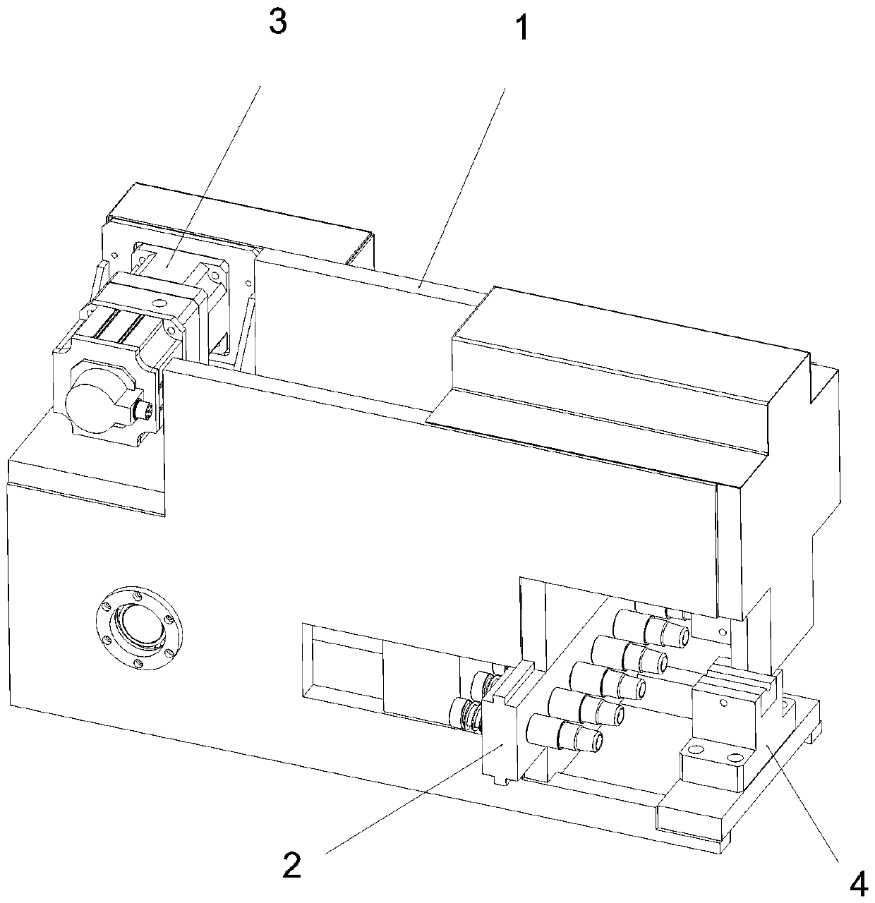
[0018] Such as figure 1 As shown, a pipe end machine that is convenient for mold change includes a controller, a frame 1, a punch device 2, a drive assembly 3 for driving the punch device 2 to push forward, and a positioning device 4 for clamping pipe fittings , the controller, the punch device 2, the driving assembly 3 and the positioning device 4 are respectively arranged on the frame 1, and the driving assembly 3 and the positioning device 4 are respectively electrically connected to the controller.

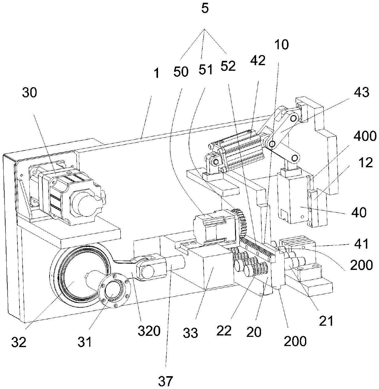
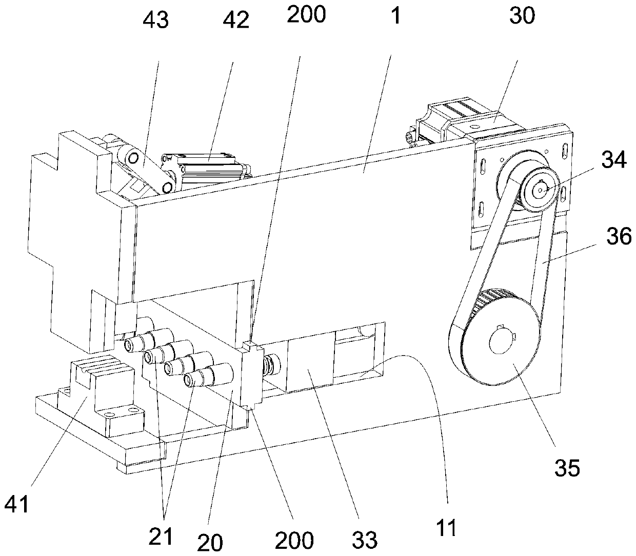
[0019] Such as figure 2 and image 3 As shown, the punch device 2 includes a movable mounting plate 20 and several punching heads 21 elastically mounted on the mounting plate 20. In this embodiment, the number of punching heads 21 is six, and along the mounting plate The longitudinal direction of 20 is arranged in parallel, and the punching heads 21 may b...


PUM


Abstract

The invention discloses a pipe end machine convenient for die changing. The pipe end machine comprises a controller, a rack, a punch device, a driving assembly used for driving the punch device to push forwards, and a positioning device used for clamping a pipe. The punch device comprises a movable mounting plate and a plurality of stamping heads elastically installed on the mounting plate. The mounting plate is slidably connected to the rack, and the sliding direction of the mounting plate is perpendicular to the stamping direction of the stamping heads. The positioning device is arranged atthe front end of the stamping direction of the stamping heads. The driving assembly drives the stamping heads to move to the positioning device. According to the pipe end machine, different stamping heads are arranged on the mounting plate, and when the stamping heads need to be replaced, the stamping heads can be replaced just by moving the mounting plate through a gear rack device; the end of the clamped pipe on the positioning device is stamped and shaped by using the stamping heads so as to solve the problems of time waste and labor waste during die changing; and the die changing efficiency is effectively improved, and stamping of different pipe end shapes is facilitated.

Description

technical field [0001] The invention relates to the field of pipe end machines, in particular to a pipe end machine which is convenient for mold change. Background technique [0002] Existing pipe end machines generally have only one stamping head, which clamps the workpiece through a mold, and the stamping head performs stamping and shaping on the ends of pipe fittings such as copper pipes. However, such a stamping mode has low stamping efficiency, and only one pipe fitting can be stamped at a time. If you need to stamp pipe ends of different shapes, you need to replace the original stamping head and install the required stamping head again. This is a time-consuming and laborious operation. The labor intensity is high, which leads to the low production efficiency of the pipe end machine, which is not conducive to the development of the enterprise. Contents of the invention [0003] The technical problem to be solved by the present invention is to provide a pipe end machi...

Claims


Application Information

Patent Timeline
Patent Type & Authority Applications(China)
IPC IPC(8): B21D37/04B21D3/10B21D19/08
CPCB21D3/10B21D19/08B21D37/04
Inventor 张彦春焦阳李笑阳
Owner 广东弘毅智能装备有限公司
Why Eureka
Try Eureka