The Clamping Device of the Upper Die Holder of the Hot Die Forging Press

A technology for hot die forging presses and clamping devices, applied in forging/pressing/hammer devices, forging/pressing/hammering machines, manufacturing tools, etc., can solve the problem of long time for replacing the upper die seat and difficulty in manufacturing and installation , low production efficiency and other problems, to achieve the effect of reducing labor intensity and production costs, low manufacturing and maintenance costs, and convenient operation

Active Publication Date: 2016-08-31
CHINA ERZHONG GRP DEYANG HEAVY IND
View PDF8 Cites 1 Cited by
  • Summary
  • Abstract
  • Description
  • Claims
  • Application Information

AI Technical Summary

Problems solved by technology

The clamping device of the upper die base of the die forging press in the prior art has the following disadvantages: since the disc spring 04 and the hydraulic cylinder 05 are all arranged in the upper die base 03, and each upper die base needs to be installed with the disc spring 04, hydraulic pressure Cylinder 05 and T-head 02 are not only difficult to manufacture and install, but also take a long time to replace the upper die holder, resulting in low production efficiency and high labor costs

Method used


Image

  • The Clamping Device of the Upper Die Holder of the Hot Die Forging Press
  • The Clamping Device of the Upper Die Holder of the Hot Die Forging Press
  • The Clamping Device of the Upper Die Holder of the Hot Die Forging Press

Examples


Embodiment Construction

[0024] The present invention will be further described below in conjunction with the accompanying drawings and embodiments.

[0025] For the convenience of description, words with orientations such as upper and lower are used in this patent application document for expression, and all words with orientation are based on the description in the drawings figure 1 represented by the orientation.

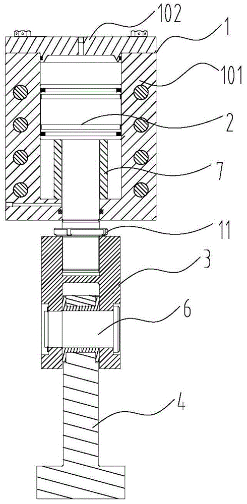
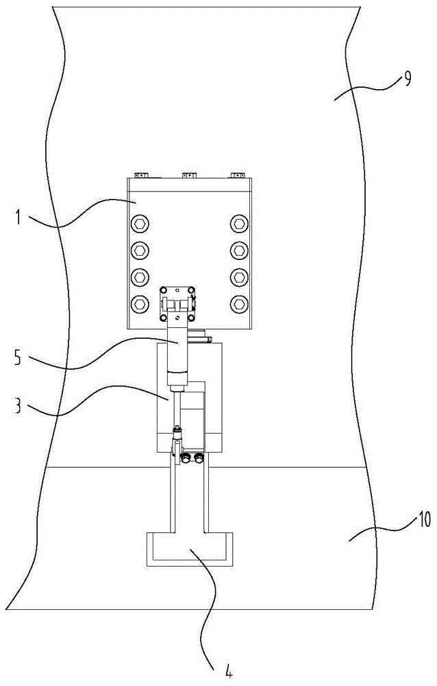
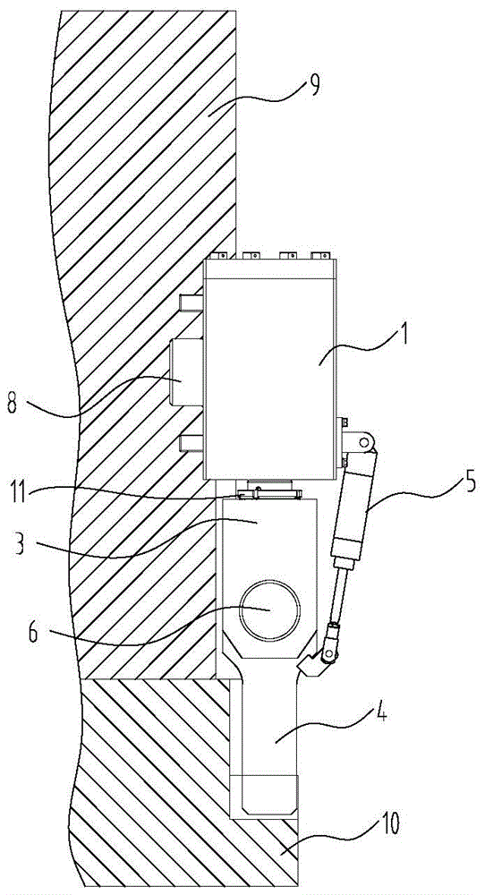
[0026] Such as figure 1 , figure 2 ,with image 3 with Figure 4 As shown, the clamping device of the upper mold base of the hot die forging press of the present invention includes a support body 1, a piston 2, an intermediate connecting body 3, a swing block 4, a swing block drive mechanism 5 and a piston drive mechanism; the support body 1 There is a closed cavity, the piston 2 is placed in the closed cavity, the piston 2 divides the closed cavity into an upper cavity and a lower cavity, and the piston rod connected with the piston 2 passes through the The bottom wall of the su...


PUM


Abstract

The invention discloses a clamping device of an upper die base of a hot die forging press and belongs to the field of forging and pressing equipment. The clamping device comprises a bearing body, a piston, an intermediate connecting body, a swinging block, a swinging block driving mechanism and a piston driving mechanism. The bearing body is provided with an enclosed cavity, the piston is arranged in the enclosed cavity and divides the enclosed cavity into an upper cavity and a lower cavity, a piston rod connected with the piston penetrates the bottom wall of the bearing body, and the piston driving mechanism drives the piston to move in the enclosed cavity. One end of the swinging block is a connecting end while the other end is a free end, one end of the intermediate connecting rod is connected with the piston rod while the other end is hinged to the connecting rod of the swinging block through a connecting pin, and the free end of the swinging block is inverted-T shaped. The swinging block driving mechanism drives the swinging block to swing around the connecting pin. The clamping device has the advantages of simple structure, convenience in operation, high die change efficiency, low manufacture and maintenance cost and the like, production efficiency is improved, and production cost is lowered.

Description

technical field [0001] The invention relates to the field of forging equipment, in particular to an upper die base clamping device of a hot die forging press. Background technique [0002] In recent years, due to the vigorous development of the automobile industry, the demand for hot forging presses for the production of various forgings in automobile parts has increased. In the production process, the mold change efficiency of the hot forging press greatly affects the production efficiency of the hot forging press. [0003] Such as Figure 5 with Image 6 As shown, the clamping device of the upper die base of the hot die forging press in the prior art is composed of a T-shaped head 02, a disc spring 04, and a hydraulic cylinder 05, which are distributed in groups on both sides of the die base. The disc spring 04 and hydraulic pressure The cylinder 05 is set in the upper mold base 03, the slider 01 is provided with a T-shaped through groove, the head of the T-shaped head 0...

Claims


Application Information

Patent Timeline
Patent Type & Authority Patents(China)
IPC IPC(8): B21J13/03
CPCB21J13/03
Inventor 余朝辉童飞
Owner CHINA ERZHONG GRP DEYANG HEAVY IND
Why Eureka
Try Eureka