Die changing trolley and die changing method thereof

A technology of mold car and mold core, applied in the field of mold change car and mold change car, which can solve the problems of mold damage and large labor intensity of mold changing equipment, so as to reduce the downtime of the line and improve the mold change. Efficiency, friction reduction effect

Pending Publication Date: 2022-03-29
JIANGXI HEMEI CERAMICS +1
View PDF0 Cites 1 Cited by
  • Summary
  • Abstract
  • Description
  • Claims
  • Application Information

AI Technical Summary

Problems solved by technology

[0006] The purpose of the present invention is to provide a mold change vehicle that solves the problem of the existing mold change equipment with high manpower intensity, easy to cause mold damage and large floor space; , The mold changing method of the mold changing car with high mold changing efficiency and ensuring the safety of the operator

Method used


Image

  • Die changing trolley and die changing method thereof
  • Die changing trolley and die changing method thereof
  • Die changing trolley and die changing method thereof

Examples


Embodiment Construction

[0051] The present invention will be described in further detail below in conjunction with accompanying drawing:

[0052] The preferred embodiments of the present invention will be described in detail below in conjunction with the accompanying drawings, so that the advantages and features of the present invention can be more easily understood by those skilled in the art, so as to define the protection scope of the present invention more clearly. The directional terms mentioned in the present invention, such as "up", "down", "front", "back", "left", "right", "top", "bottom", etc., are only for reference to the attached drawings. direction. Therefore, the directional terms used are used to illustrate and understand the present invention, but not to limit the present invention.

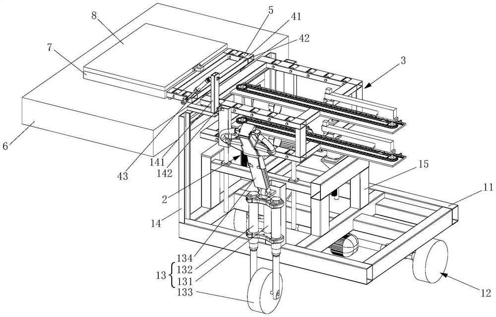
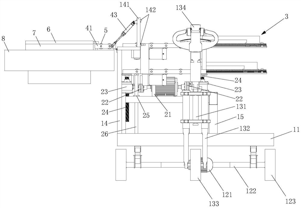
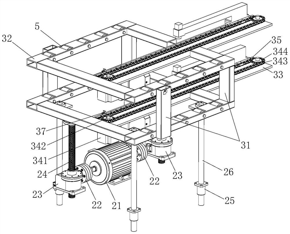
[0053] see figure 1 , figure 2 As shown, the present invention provides a mold changing vehicle, comprising a driving mechanism, a lifting mechanism 2 installed on the driving mechanism, a mold chang...


PUM


Abstract

The invention relates to a die changing trolley and a die changing method thereof, the die changing trolley comprises a driving mechanism, a lifting mechanism mounted on the driving mechanism and a die changing mechanism driven by the lifting mechanism to lift, a mounting support is further fixedly arranged on the side, close to the die changing end, of the driving mechanism, and a rail connecting mechanism is mounted at the upper end of the mounting support; the die changing mechanism comprises at least two layers of die changing components which are arranged in parallel through a support. According to the die changing trolley combined with the die changing method, die core changing can be achieved through single equipment, the changing time is shortened, and the changing efficiency is improved.

Description

technical field [0001] The invention relates to the field of mold core replacement and transfer of ceramic tile presses, in particular to a mold changing vehicle and a mold changing method of the mold changing vehicle. Background technique [0002] In the ceramic tile manufacturing industry, large-tonnage hydraulic presses are one of the essential equipment for adobe molding. After the ceramic raw materials are ball milled and sprayed into powder, they are evenly filled into the cavity of the press through the distributor, and the bricks are formed under the pressure of the upper and lower dies of the large-tonnage hydraulic press, and then dried, glazed and fired. Waiting for the process. During the pressing process, the surface texture of the adobe depends on the engraved patterns on the surface of the upper and lower mold cores. When products with different textures need to be produced, the press cores need to be replaced. During the replacement process, the press proces...

Claims


Application Information

Patent Timeline
Patent Type & Authority Applications(China)
IPC IPC(8): B28B17/00B28B7/00B66F3/46B66F3/08B66F3/44
CPCB28B17/009B28B17/0063B28B17/00B28B7/0097B28B7/0064B28B7/0002B66F3/46B66F3/08B66F3/44
Inventor 吴业荣李忠民邓家成吴家良曾昭云李勇进魏帅丁爽
Owner JIANGXI HEMEI CERAMICS
Why Eureka
Try Eureka