Crane and hydraulic system thereof for controlling composite motion

A compound action and hydraulic system technology, applied in the field of hydraulic systems, can solve problems such as the adverse effects of the actuator, the constant movement speed of the actuator, and the adjustment of the execution speed of the actuator.

Active Publication Date: 2013-12-04
HEFEI SMARTER TECH GROUP CORP
7 Cites 2 Cited by

AI-Extracted Technical Summary

Problems solved by technology

[0004] However, when the crane in the prior art is performing compound actions, if an actuator generates a large load pressure in an instant, the hydraulic pressure in the load oil circuit will be greater than the hydraulic pressure in the main oil circuit connected to the hydraulic pump. Pressure, if the hydraulic oil flow of the actuator remains unchanged at this time, that is, the movement speed of the actuator re...

Abstract

The invention discloses a hydraulic system for controlling composite motion of a crane. The hydraulic system comprises a first pressure sensor for sensing hydraulic pressure of a load oil-way, a second pressure sensor for sensing hydraulic pressure of a main oil-way, an operation control module in communication-capable connection with the first pressure sensor and the second pressure sensor, a main rising control valve for controlling aperture of a main rising multi-way valve, an auxiliary rising control valve for controlling aperture of an auxiliary multi-way valve and a luffing control valve for controlling aperture of a luffing multi-way valve. The operation control module is respectively in communication-capable connection with the main rising control valve, the auxiliary rising control valve and the luffing control valve. According to the arrangement, execution speed of the execution mechanism in the hydraulic system for controlling composite motion of the crane provided by the invention can be adjusted properly according to changes of load pressure. The invention also discloses a crane comprising the above hydraulic system for controlling composite motion of the crane.

Application Domain

Load-engaging elements

Technology Topic

Pressure sensorControl valves +2

Image

  • Crane and hydraulic system thereof for controlling composite motion

Examples

  • Experimental program(1)

Example Embodiment

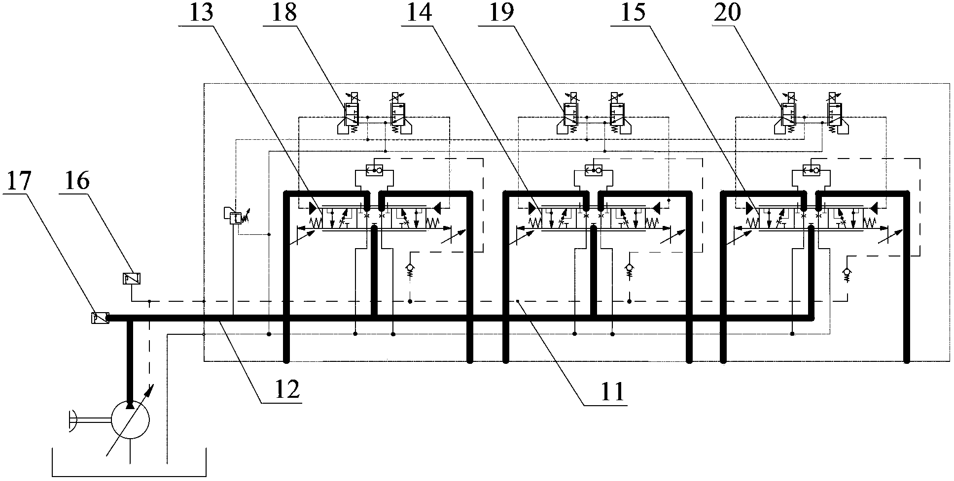
[0016] The invention provides a hydraulic system for controlling compound actions of a crane, and the execution speed of its actuator can be properly adjusted according to the change of load pressure. The present invention also provides a crane including the above-mentioned hydraulic system for controlling compound actions of the crane.
[0017] The technical solutions of the present invention will be clearly and completely described below in conjunction with specific embodiments of the present invention and accompanying drawings. Apparently, the described embodiments are only some of the embodiments of the present invention, not all of them. Based on the embodiments of the present invention, all other embodiments obtained by persons of ordinary skill in the art without making creative efforts belong to the protection scope of the present invention.
[0018] Please refer to figure 1 , figure 1 It is a schematic structural diagram of the hydraulic system for controlling the compound action of the crane in the specific embodiment of the present invention.
[0019] A hydraulic system for controlling compound movements of a crane provided in this specific embodiment includes a load oil circuit 11, a main oil circuit 12, a main lift multi-way valve 13 for controlling the main lift execution cylinder, a Auxiliary lift multi-way valve 14 of the executive oil cylinder and main lift and amplitude multi-way valve 15 for controlling the amplitude of the executive oil cylinder.
[0020] It should be noted that the hydraulic system for controlling compound movements of the crane provided in this specific embodiment also includes a first pressure sensing device 16 for sensing the hydraulic pressure of the load oil circuit 11 and a second pressure sensing device 16 for sensing the hydraulic pressure of the main oil circuit 12 . The pressure sensing device 17, the arithmetic control module (not shown in the figure) communicatively connected with the first pressure sensing device 16 and the second pressure sensing device 17, is used to control the opening degree of the main lifting multi-way valve 13 The main lift control valve 18 , the auxiliary lift control valve 19 used to control the opening degree of the auxiliary lift multi-way valve 14 , and the amplitude control valve 20 used to control the opening degree of the amplitude-changing multi-way valve 15 . Wherein, the arithmetic control module is communicably connected with the main lift control valve 18 , the auxiliary lift control valve 19 and the luffing control valve 20 respectively.
[0021] It should be understood that the execution speeds of the main lifting executive oil cylinder, the auxiliary lifting executive oil cylinder and the luffing executive oil cylinder are determined by the opening degrees of the main lifting multi-way valve 13, the auxiliary lifting multi-way valve 14 and the luffing multi-way valve 15 respectively. It is determined that the main lift control valve 18, the auxiliary lift control valve 19 and the luffing control valve 20 provided in this specific embodiment can control the main lift multi-way valve 13, the auxiliary lift multi-way valve 14 and the luffing multi-way valve respectively. The degree of opening of the road valve 15.
[0022] In this way, when the crane performs composite actions, the first pressure sensing device 16 is used to sense the hydraulic pressure of the load oil circuit 11, the second pressure sensing device 17 is used to sense the hydraulic pressure of the main oil circuit 12, and the first pressure sensing device 16 and the second pressure sensing device 17 transmit the sensed pressure to the calculation control module (not shown in the figure), and the calculation control module compares the magnitude of the pressure transmitted by the two. If the load of one of the executive oil cylinders becomes larger instantaneously, the hydraulic pressure sensed by the first pressure sensing device 16 is greater than the hydraulic pressure sensed by the second pressure sensing device 17, and the operation control module will send the main lifting control valve 18 and the auxiliary lifting control valve 19 and the luffing control valve 20 send control signals, so that the main lift control valve 18 controls to reduce the opening of the main lift multi-way valve 13, and the auxiliary lift control valve 19 controls to reduce the opening of the auxiliary lift multi-way valve 14. Degree, luffing control valve 20 controls and reduces the opening of luffing multi-way valve 15, and then reduces the flow rate of the main lifting executive oil cylinder, the auxiliary lifting executive oil cylinder and the luffing executive oil cylinder, so as to achieve the purpose of speed reduction.
[0023] Therefore, in the hydraulic system for controlling compound movements of the crane provided in this specific embodiment, the execution speed of the actuator can be properly adjusted according to the change of the load pressure.
[0024] The main lift control valve 18 , the auxiliary lift control valve 19 and the luffing control valve 20 provided in this specific embodiment may specifically be proportional valves. It should be noted that there are two proportional valves for controlling the opening of the main lift multi-way valve 13, which are respectively used to control the main lift multi-way valve 13 when the main lift cylinder is extended and retracted. flow size. Similarly, there are two proportional valves for controlling the auxiliary lifting control valve 19 and controlling the luffing control valve 20 .
[0025] Of course, the main lift control valve 18 , the auxiliary lift control valve 19 and the luffing control valve 20 provided in this specific embodiment can also be other types of valve devices, for example, they can be specifically servo valves.
[0026] In addition, for the convenience of installation, the first pressure sensing device 16 provided in this specific embodiment can be arranged at the oil port of the load oil circuit 11 , and the second pressure sensing device is arranged at the hydraulic pump outlet of the main oil circuit 12 . Of course, the first pressure sensing device 16 and the second pressure sensing device 17 can also be arranged in other positions of the load oil circuit 11 and the main oil circuit 12 respectively, as long as they can normally sense the hydraulic pressure of the load oil circuit 11 and the main oil circuit 12. Can.
[0027] This specific embodiment also provides a crane, including the hydraulic system for controlling the combined action of the crane as described in any one of the above. Similarly, in the crane provided by this specific embodiment, the execution speed of its actuator can be properly adjusted according to the change of the load pressure, and the derivation process of the beneficial effect is generally similar to the derivation process of the beneficial effect brought by the above-mentioned hydraulic system. Therefore, this article will not repeat them.
[0028]Above, a kind of crane provided by this specific embodiment and its hydraulic system for controlling composite actions have been introduced in detail. In this paper, specific examples have been used to illustrate the principle and implementation of the present invention. The description of the above embodiments is only for Help to understand the method and core idea of ​​the present invention. It should be pointed out that for those skilled in the art, without departing from the principle of the present invention, some improvements and modifications can be made to the present invention, and these improvements and modifications also fall within the protection scope of the claims of the present invention.

PUM

no PUM

Description & Claims & Application Information

We can also present the details of the Description, Claims and Application information to help users get a comprehensive understanding of the technical details of the patent, such as background art, summary of invention, brief description of drawings, description of embodiments, and other original content. On the other hand, users can also determine the specific scope of protection of the technology through the list of claims; as well as understand the changes in the life cycle of the technology with the presentation of the patent timeline. Login to view more.
Why Eureka
Try Eureka